Clip-on Heater

a heater and clip-on technology, applied in the field of clip-on heaters, can solve the problems of affecting the heat dissipation effect of the heater, affecting the heat dissipation efficiency of the heater, etc., to achieve the effect of preventing the capture of air bubbles, and reducing the heat dissipation ra

Inactive Publication Date: 2012-04-05
AURORA INSTR
View PDF3 Cites 28 Cited by
  • Summary
  • Abstract
  • Description
  • Claims
  • Application Information

AI Technical Summary

Benefits of technology

[0026]Heat is typically generated by resistance heating of a thin serpentine conductor pattern laminated in a flexible polymer sandwich. Specific patterns, resistance values, and other characteristics of the heater element are not material to this invention, so long as sufficient heat can be generated in a reasonable time to heat the enclosure and the cable and result in proper completion of the desired process. Generally the pattern is designed to heat faster in the center, so that the proximate center of the heat shrink sleeve heats and shrinks first, so as to prevent the capture of air bubbles.
[0027]Typically the heater element is laminated onto a formative plate or shell, usually of metal, although electrically insulated from it. The metal shell is formed substantially in the shape of a semi-cylinder, much longer than wide, approximately in a U or C shape. The shell provides mechanical strength and stability to the heater and spreads the heat quickly and uniformly due to its thermal conductivity.
[0028]Adjacent to the heater and metal shell is located a temperature sensing device, typically a thermistor, resistance temperature device (RTD), or thermocouple. This gives the control circuitry the ability to monitor the temperature inside the enclosure and control the heating properly.
[0030]In some embodiments two halves of a basically cylindrical housing are activated by grippers and a built-in spring, much like an ordinary clothes pin (which is also designed easily to clip onto a “cable”, i.e. a clothes line). The grippers allow a user easily to open the two halves of the housing to orient it onto a cable, and when the grippers are released the built-in spring urges the two halves together to complete the closure and attachment onto the cable.

Problems solved by technology

The newer thinner wires sometimes do not seal properly in existing grommets and glands, potentially allowing leakage of contaminants into the connector.
Optical fibers must be stripped of their protective coatings and cleaned to bare glass before splicing, but this process leaves the fibers weakened and vulnerable to damage from humidity, tension, bending, and other stresses.
Heat guns have advantages of low cost, common availability, and some control of temperature, and they can often be applied to cables in situ, but they have serious disadvantages.
In explosive atmospheres typical of many locations, such as fuel depots, aircraft hangers and flight decks, refineries, mines, and mills, the red hot resistance heating coils pose an unacceptable risk of igniting flammable vapor.
Even in safe environments, the heat gun requires considerable expertise and attentiveness on the part of the user.
Heating the heat shrink sleeve too hot or too long may damage the plastic coatings on the cable, wire, or fiber, or even the sleeve itself.
Heating unevenly, so as to shrink the ends of the sleeve before the center, can trap air bubbles inside, which in the long run will lead to bending stresses on an optical fiber and possibly failure.
When a cable is in a hard-to-reach location it may be difficult or impossible to maneuver the heat gun so as to blow and heat evenly on all sides, with resulting uneven and possibly incomplete shrinkage of the heat shrink sleeve.
Inadvertent under-heating may leave the sleeve incompletely sealed and leave the wire or fiber subject to environmental attack.
a defective result may be accepted and left in place inadvertently, only to fail later when the consequences may be serious and the cost of repair high.
And because the heat gun must transmit heat to an object by blowing air, it must consume a large amount of power relative to what is needed intrinsically to shrink a heat shrink sleeve, making it impractical to power with a portable battery.
Among the serious disadvantages, however, are typically much higher cost than a heat gun and the fact that the oven is bench-mounted or substantially packaged.
Many heat ovens even package their own batteries internally, further adding to the size and weight of the over all device3.
But in many other situations particularly including repair it is inconvenient, impractical, or even impossible to move the cable from where it happens to be and bring it to the oven, compact though the oven be.
However, these inventions all envision the heating element wound entirely around the object to be heated, and thus either not removable at all afterward or only with difficulty.
These heaters are by no means either “clip-on” or removable after use.
Assemblies according to this invention are clearly bulky, heavy, and unsuitable for cramped or limited spaces or for suspending on cables with their own weight.
What has been lacking in the prior art is a heater for processing cables which is small and light to be disposed directly onto the cable and suspended under its own weight.
A further need is for a device to heat-treat cables in situ, particularly for repair, without the need to disturb them, which may be extremely difficult, expensive, or dangerous.

Method used


Image

  • Clip-on Heater
  • Clip-on Heater
  • Clip-on Heater

Examples


Embodiment Construction

[0038]This invention relates to a device and method for causing desirable changes in the characteristics of a cable, wire, or fiber by the application of heat. Commonly cables are reinforced, insulated, stiffened, and the like by the application of an adhesive-lined sleeve which, when heated, shrinks substantially to tighten and seal around a particular portion of the cable. This invention addresses means of performing this operation which are unusually small, light-weight, and disposed to be applied directly onto the cable without moving it from where it might already be in service.

[0039]The following detailed description of preferred embodiments is intended to be illustrative, not limiting. It will be understood that alternative applications will be readily apparent to those skilled in the art, which are not described herein in detail but which nevertheless fall under the coverage of the appended claims.

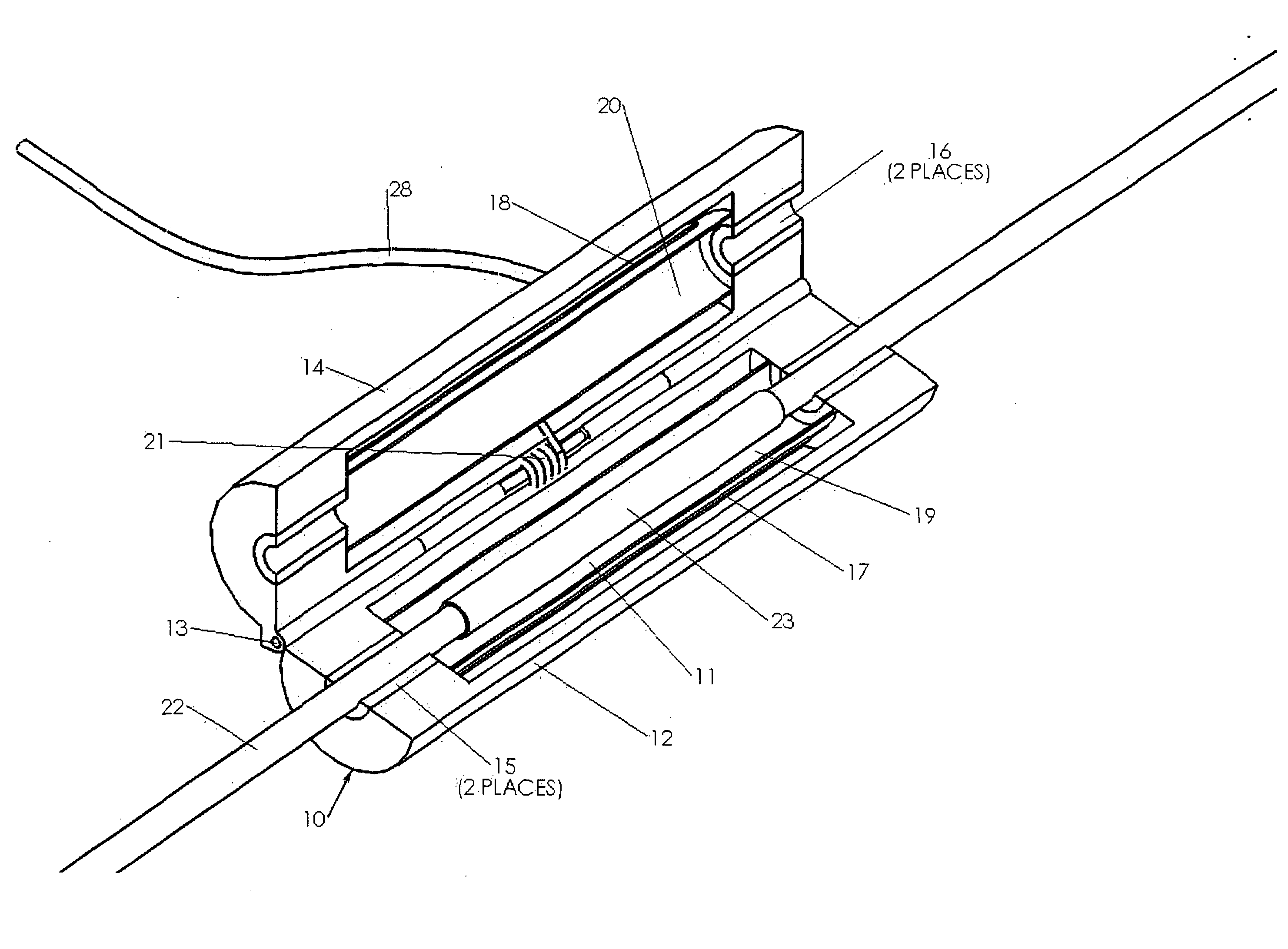
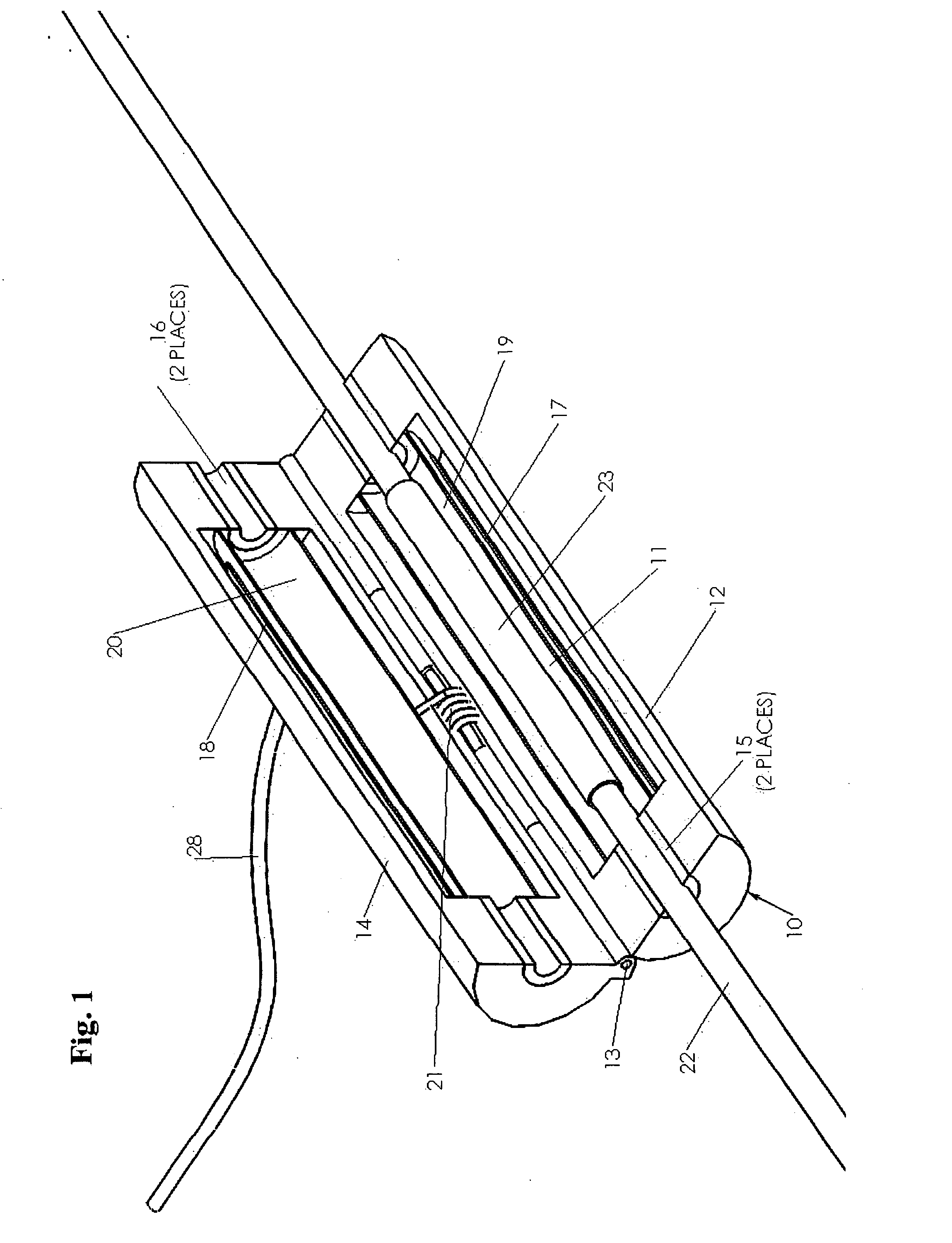
[0040]FIG. 1 illustrates a first embodiment of a clip-on heater 10. The struct...


PUM


Abstract

A device is disclosed for the heat processing of cables, wires, fibers, and the like which is small, light, and configured to be disposed temporarily directly on the cable to be heated in situ. Typically the device comprises a heat generation element or elements and supporting shells arranged so as to form an elongated cavity, a housing to provide an insulating enclosure around the cable so as to form a heated chamber, temperature sensing means to monitor the heating for closed-loop control, and means to enable the heater to hold itself onto the cable or wire in situ. Power and control means with electrical processing capability are provided to supply power to the heater, monitor the temperature inside the heater cavity, and govern the time and temperature which the device applies to the cable or wire in order to process it, for instance to apply a heat shrink sleeve.

Description

FIELD OF THE INVENTION[0001]This invention relates to a device for causing desirable changes in the characteristics of a cable, wire, or fiber by the application of heat. Commonly cables are reinforced, insulated, stiffened, and the like by the application of an adhesive-lined sleeve which, when heated, shrinks substantially to tighten and seal around a particular portion of the cable. This invention addresses means of performing this operation which are unusually small, light-weight, and configured to be applied directly onto the cable without moving it from where it might already be in service or applying any undue stresses.DESCRIPTION OF THE PRIOR ART[0002]Heat shrink sleeves have been used on cables and wires of various kinds for many years. Such sleeves commonly consist of a tube of polyolefin which is lined internally with a smaller tube or layer of adhesive, commonly polyamide or ethyl vinyl acetate (EVA) “hot melt” glue. There is an entire military specification for these pr...

Claims


Application Information

Patent Timeline
Patent Type & Authority Applications(United States)
IPC IPC(8): H05B1/00H05B3/06
CPCG02B6/2558H05B3/44H05B1/0291
Inventor BUSH, SIMON PETERCABATO, NELLIE LUNAWESSON, LAURENCE NATHANIEL
Owner AURORA INSTR
Why Eureka
Try Eureka