Mold for Forming a Molding Member and Method of Fabricating a Molding Member Using the Same

a molding member and molding technology, applied in the direction of manufacturing tools, food shaping, semiconductor/solid-state device details, etc., can solve the problems of reducing the uniformity and efficiency of light emitted through the molding member, and the molding member is not easy to cur

Inactive Publication Date: 2008-10-30
SEOUL SEMICONDUCTOR
View PDF11 Cites 22 Cited by
  • Summary
  • Abstract
  • Description
  • Claims
  • Application Information

AI Technical Summary

Problems solved by technology

The gas captured in the molding material may cause inferior curing of the molding member

Method used


Image

  • Mold for Forming a Molding Member and Method of Fabricating a Molding Member Using the Same
  • Mold for Forming a Molding Member and Method of Fabricating a Molding Member Using the Same
  • Mold for Forming a Molding Member and Method of Fabricating a Molding Member Using the Same

Examples


Embodiment Construction

[0024]Hereinafter, preferred embodiments of the present invention will be described in detail with reference to the accompanying drawings. The following embodiments are provided only for illustrative purposes so that those skilled in the art can fully understand the spirit of the present invention. Therefore, the present invention is not limited to the following embodiments but may be implemented in other forms. In the drawings, the widths, lengths, thicknesses and the like of elements are exaggerated for convenience of illustration. Like reference numerals indicate like elements throughout the specification and drawings.

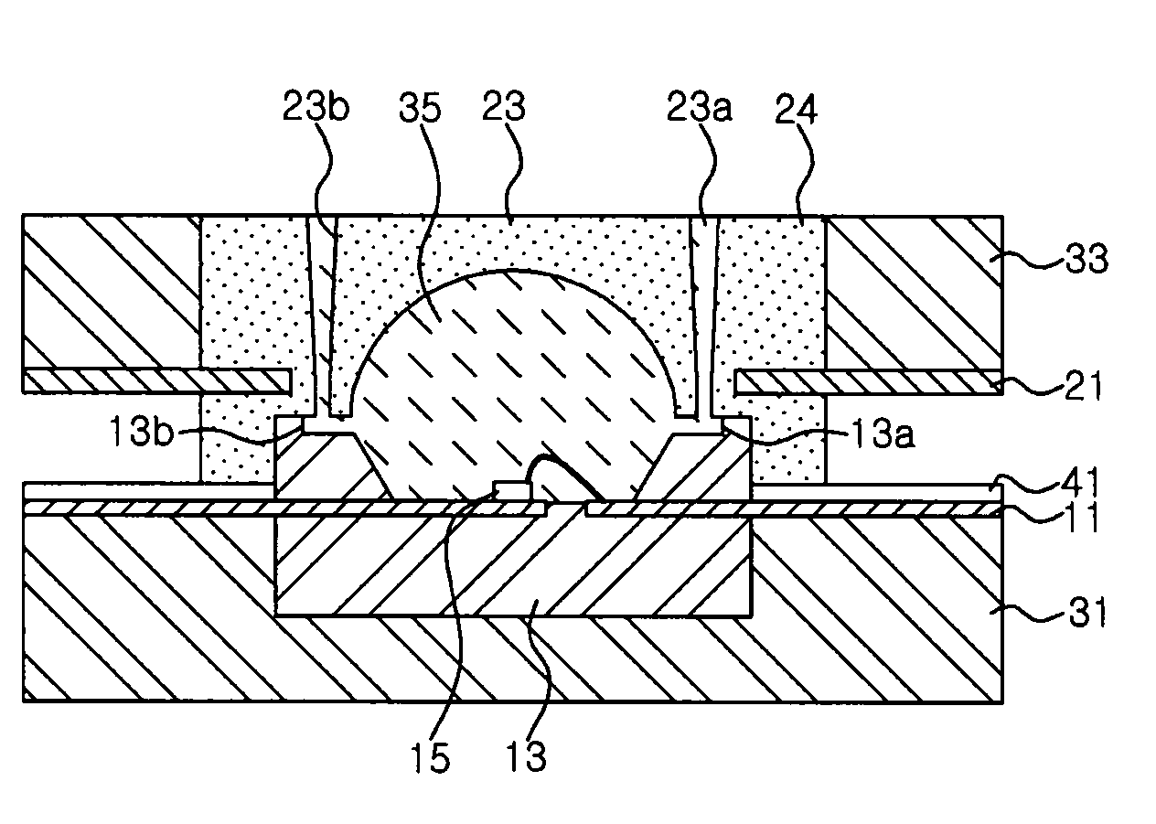
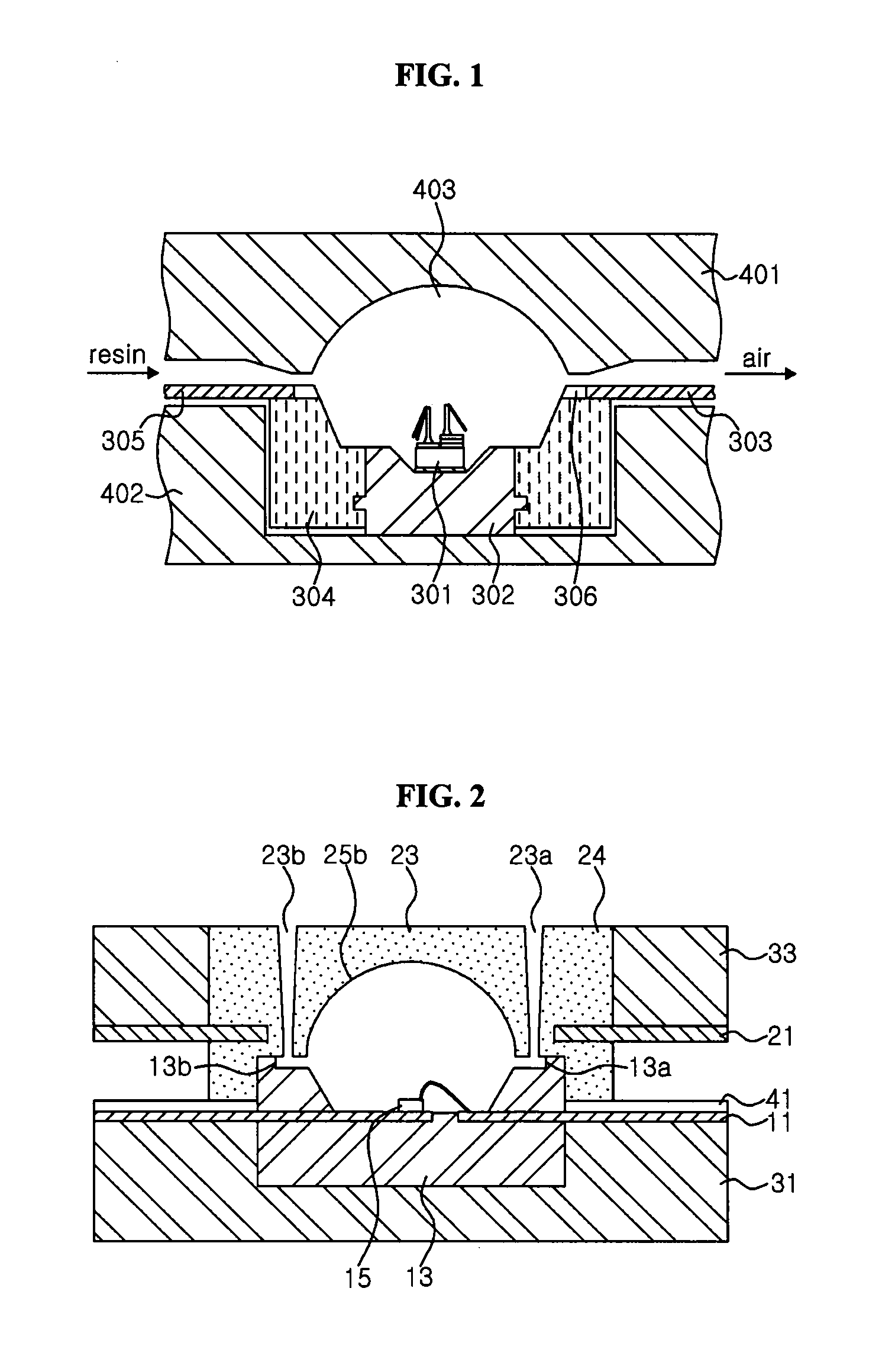
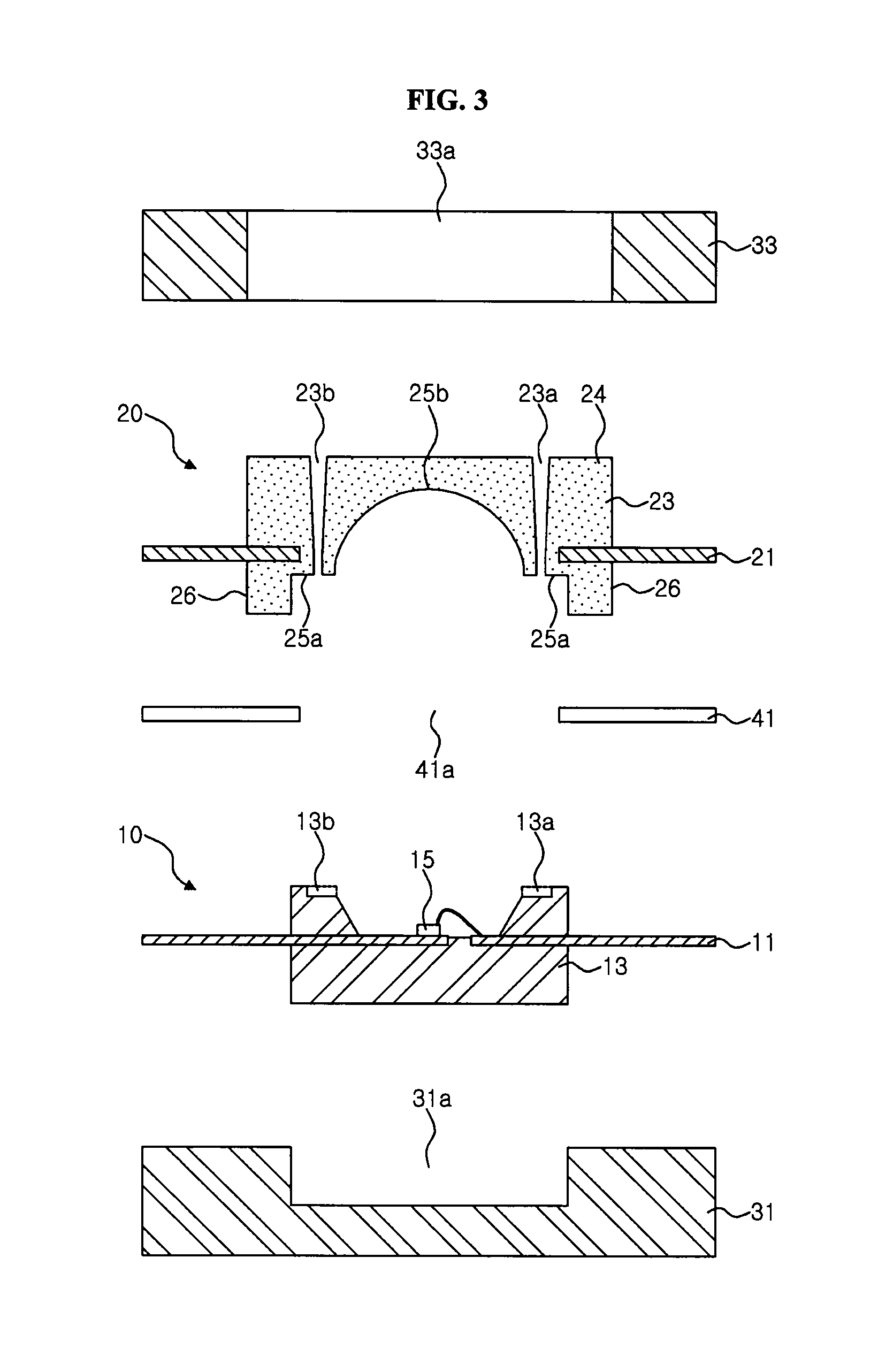
[0025]FIGS. 2 to 5 are sectional views illustrating a method of forming a molding member according to an embodiment of the present invention. Here, FIG. 3 is an exploded sectional view of FIG. 2.

[0026]Referring to FIGS. 2 and 3, a mold 20 for forming a molding member on a package is prepared. The mold 20 has an upper surface 24, and a lower surface having an outer p...


PUM


Abstract

There are provided a mold for forming a molding member and a method for forming a molding member using the same. The mold includes an upper surface, and a lower surface having an outer peripheral surface and a concave surface surrounded by the outer circumference. Injection and discharge holes extend from the upper surface to the lower surface. Accordingly, after the mold and the package are coupled so that the discharge hole is directed upward, a molding member can be formed on the package by injecting the molding material through the injection hole, whereby it is possible to prevent air bubbles from being captured in the molding member.

Description

RELATED APPLICATIONS[0001]This application is a U.S. national phase application of PCT International Application No. PCT / KR2006 / 002462, filed Jun. 26, 2006, which claims priority of Korean Patent Application No. 10-2005-0063361, filed Jul. 13, 2005, the contents of which are incorporated herein by reference in their entirety.FIELD OF THE INVENTION[0002]The present invention relates to a mold and a method for forming a molding member using the same, and more particularly, to a mold for forming a lens-shaped molding member on a package and a method for forming a molding member using the same.BACKGROUND OF THE INVENTION[0003]Generally, a light emitting device includes a package with an LED (Light Emitting Diode) mounted thereon and a lens for covering the LED for improving a light emission efficiency within a certain range of viewing angles. This lens may be produced in advance by casting or the like and then coupled on the package, but the lens and package are weakly adhered. Accordin...

Claims


Application Information

Patent Timeline
IPC IPC(8): H01L33/00B29C45/34
CPCB29C33/10B29C39/006B29C39/10B29C39/26B29C45/14655B29C45/34B29L2011/00H01L21/565H01L23/49861H01L33/52H01L2224/48091H01L2224/48247H01L2224/49107H01L2924/00014H01L21/56
Inventor JUNG, JUNG HWA
Owner SEOUL SEMICONDUCTOR
Why Eureka
Try Eureka