Digital pulse width modulation circuit and working method

A digital pulse width modulation and circuit technology, applied in the direction of pulse duration/width modulation, electrical components, output power conversion devices, etc., can solve problems such as difficult to achieve high-frequency circuit performance, digital technology obstacles, complex structure, etc. Achieve the effect of improving resource utilization and circuit performance, improving fine delay clock signal, and reducing response time

Active Publication Date: 2020-01-07
HEFEI UNIV OF TECH
View PDF11 Cites 10 Cited by
  • Summary
  • Abstract
  • Description
  • Claims
  • Application Information

AI Technical Summary

Problems solved by technology

In recent years, high-resolution digital pulse width modulation (DPWM) has been a research hotspot in the field of digital switching power supplies. Traditional digital pulse width modulators and their control methods are in terms of time resolution, dynamic response speed, power consumption and resource occupation. The defect has always been the main obstacle to the application of digital technology in the field of switching power supply
Although a single DPWM module based on ordinary binary counter and comparator structure is simple to implement, the limit cycle oscillation caused by insufficient resolution will seriously affect the quality of the output voltage of the switching power converter
[0003] Due to its specific working mechanism, the DPWM based on the counter and comparator structure is difficult to achieve high frequency and relies too much on the performance of the clock generation circuit. The overall complexity and cost of the circuit are too high, which is not conducive to large-scale applications.
However, using the fine phase shift function of the high-performance clock management module to improve the time resolution of DPWM has the defect of long dynamic response time, which cannot meet the real-time requirements of high-performance switching converters.
[0004] At present, the time resolution of ordinary commercial digital pulse width modulators is low and the control method is single. The time resolution capability of mainstream products is between several nanoseconds and hundreds of nanoseconds, while high-precision pulse width modulation chips are expensive and complex in structure. , is not conducive to the promotion of the use of

Method used


Image

  • Digital pulse width modulation circuit and working method
  • Digital pulse width modulation circuit and working method
  • Digital pulse width modulation circuit and working method

Examples


Embodiment Construction

[0036] In order to make the technical means, creative features, goals and effects achieved by the present invention easy to understand, the technical solutions in the embodiments of the present invention will be clearly and completely described below in conjunction with the accompanying drawings in the embodiments of the present invention. Obviously, the The described embodiments are only some, not all, embodiments of the present invention. Based on the embodiments of the present invention, all other embodiments obtained by persons of ordinary skill in the art without creative efforts fall within the protection scope of the present invention.

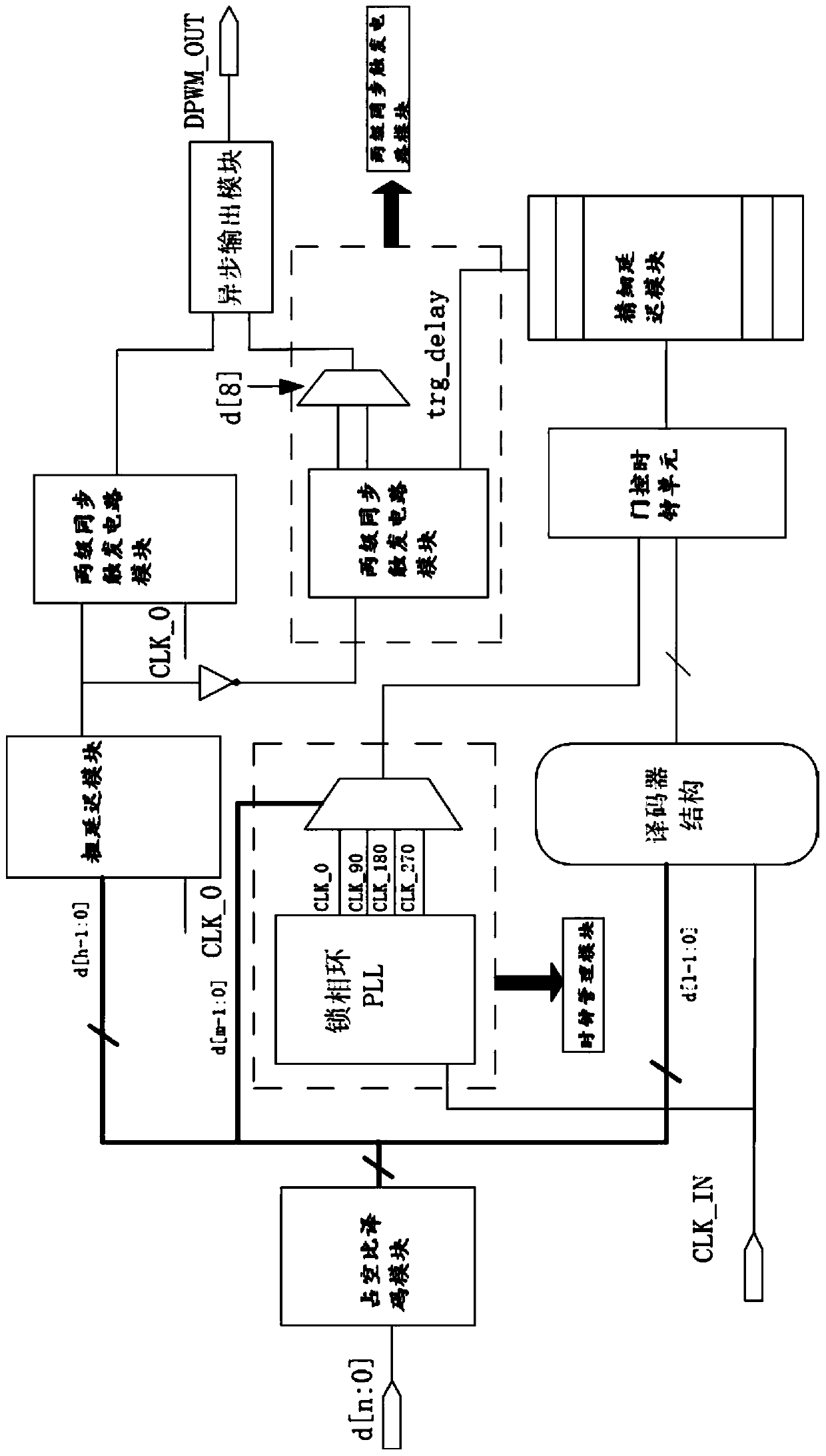
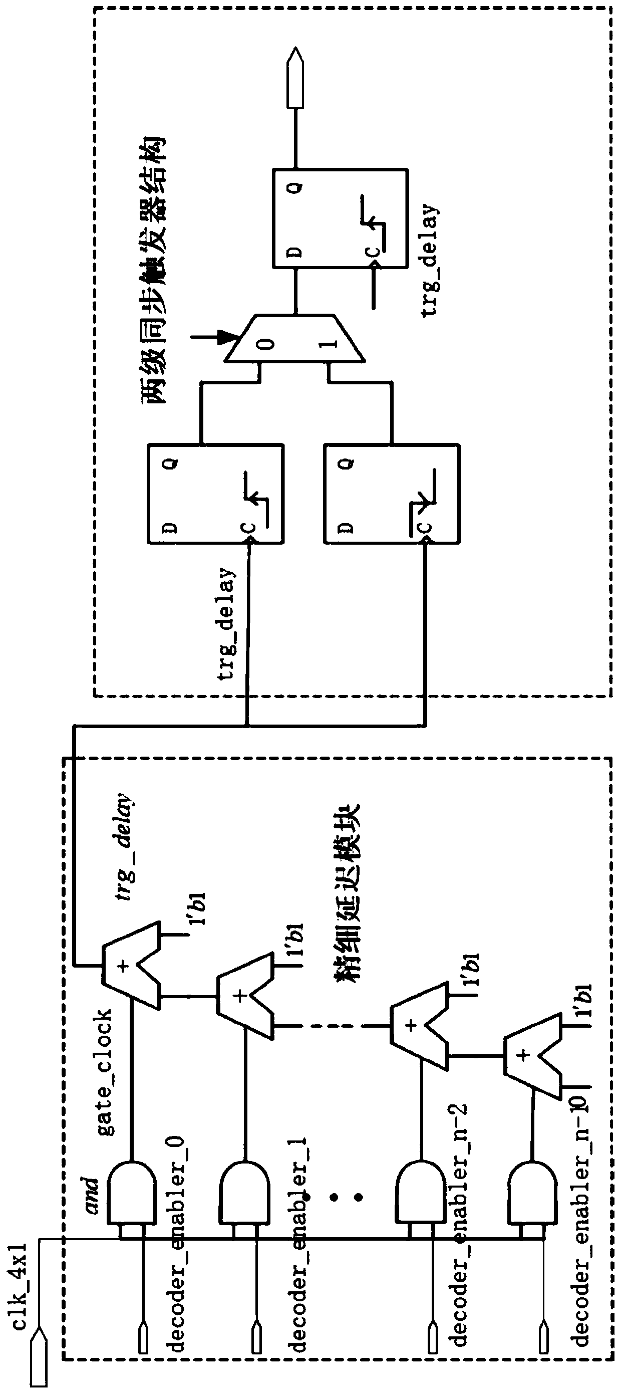
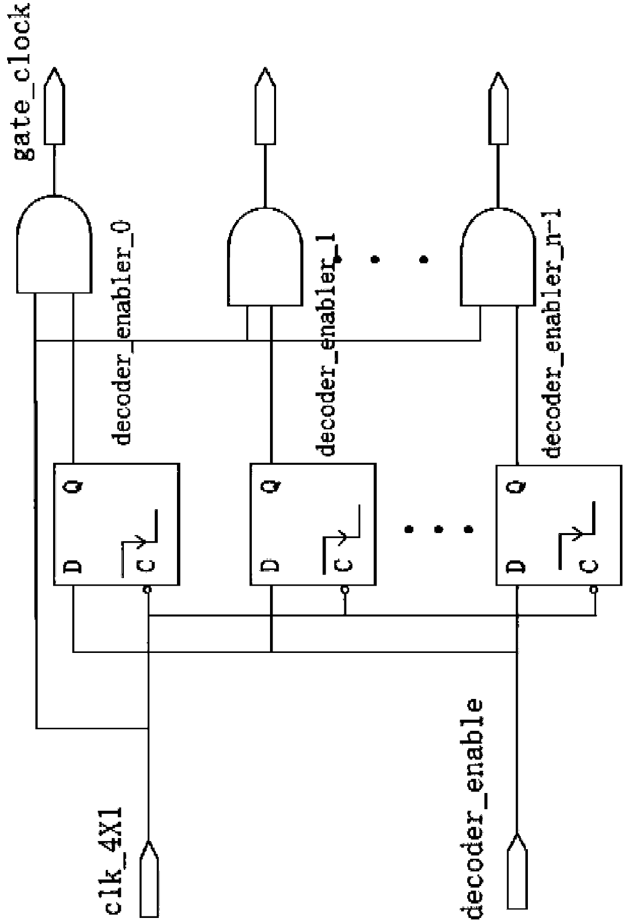
[0037] In the present invention, taking a 12-bit digital pulse width modulation circuit and its working method as an example, a digital pulse width modulation circuit is proposed, including a counter-based coarse delay module, a phase-locked loop-based clock management module, and a two-stage synchronous trigger circuit module , Fine dela...


PUM


Abstract

The invention relates to the technical field of power supply management chips, in particular to a digital pulse width modulation circuit, which comprises a coarse delay module based on a counter, a clock management module based on a phase-locked loop, a two-stage synchronous trigger circuit module, a fine delay module based on a carry chain unit, a duty ratio decoding module and a gated clock unit. The invention has the beneficial effects that two-stage synchronous triggers are used on two main paths of high-level output triggering and asynchronous fine phase shift clock signals. Delay of different paths is balanced. Meanwhile, the rising edge of the input clock is prevented from being very close to the rising edge of the fine phase shift clock trigger signal. The clock management module is used for obtaining four paths of signals with the phase difference of 90 degrees, and after the four paths of phase shift clock signals pass through the gating clock unit and the fine delay module,the response speed of digital switch converter voltage regulation and control is increased.

Description

technical field [0001] The invention relates to the technical field of power management chips, in particular to a digital pulse width modulation circuit and a working method. Background technique [0002] Digital Pulse Width Modulation (DPWM) is a control method in DC-DC converters. This method controls the output voltage by adjusting the turn-on and turn-off time of circuit switching devices to achieve a stable value. When the circuit is stable, the switching circuit operates at a fixed duty cycle. And when encountering external disturbance, the output voltage will undergo a series of changes. At this time, the circuit will use DPWM to adjust the duty cycle of the PWM wave through sampling and digital compensation to adjust the turn-on and turn-off time of the switch tube, so that the circuit can reach the final stable state. The pulse width modulation method realizes the switching off of the power tube under the action of a fixed frequency signal, and obtains a stable ou...

Claims


Application Information

Patent Timeline
Patent Type & Authority Applications(China)
IPC IPC(8): H03K7/08H02M1/14
CPCH03K7/08H02M1/14H02M1/0012Y02B70/10
Inventor 张章崔明辉唐泽晨程心解光军
Owner HEFEI UNIV OF TECH
Why Eureka
Try Eureka