Molding die for molding boot for constant velocity joint

a constant velocity joint and molding die technology, which is applied in the field of molding dies for molding boots for constant velocity joints, can solve the problems that the inner peripheral surface of the boot for constant velocity joints cannot be molded with high precision and cannot be said that the blow molding method is optimal, so as to achieve the effect of preventing burrs

Inactive Publication Date: 2014-05-29
JTEKT CORP
View PDF2 Cites 10 Cited by
  • Summary
  • Abstract
  • Description
  • Claims
  • Application Information

AI Technical Summary

Benefits of technology

[0009]An object of the invention is to provide a molding die for molding a boot for a constant velocity joint, which can prevent burrs from being generated in a compact molded by injection molding.

Problems solved by technology

Thus, in the blow molding method, an inner peripheral surface of the boot for a constant velocity joint cannot be molded with high precision.
Therefore, it cannot be said that the blow molding method is optimal as the method of molding the boot for a constant velocity joint, which requires a precise bellows structure.

Method used


Image

  • Molding die for molding boot for constant velocity joint
  • Molding die for molding boot for constant velocity joint
  • Molding die for molding boot for constant velocity joint

Examples


Embodiment Construction

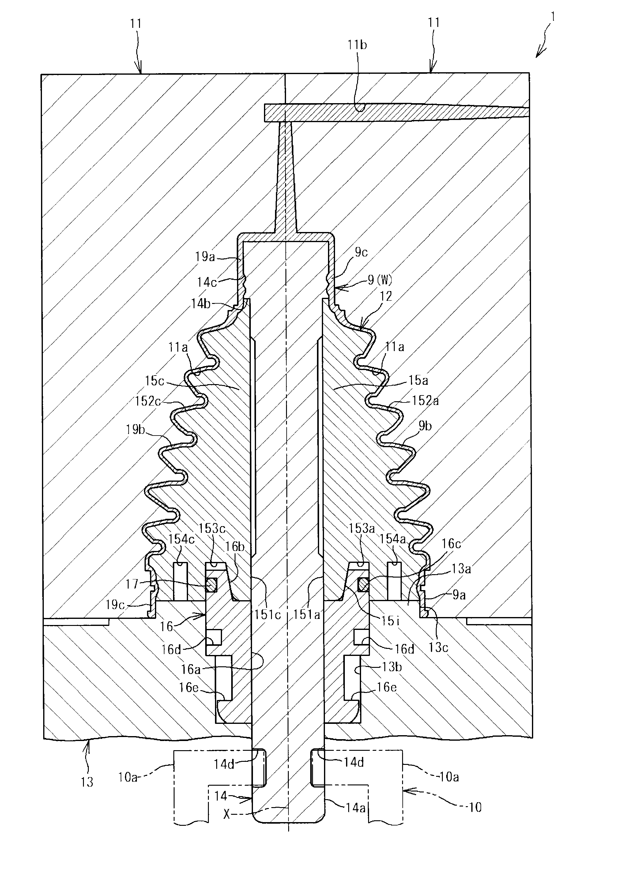
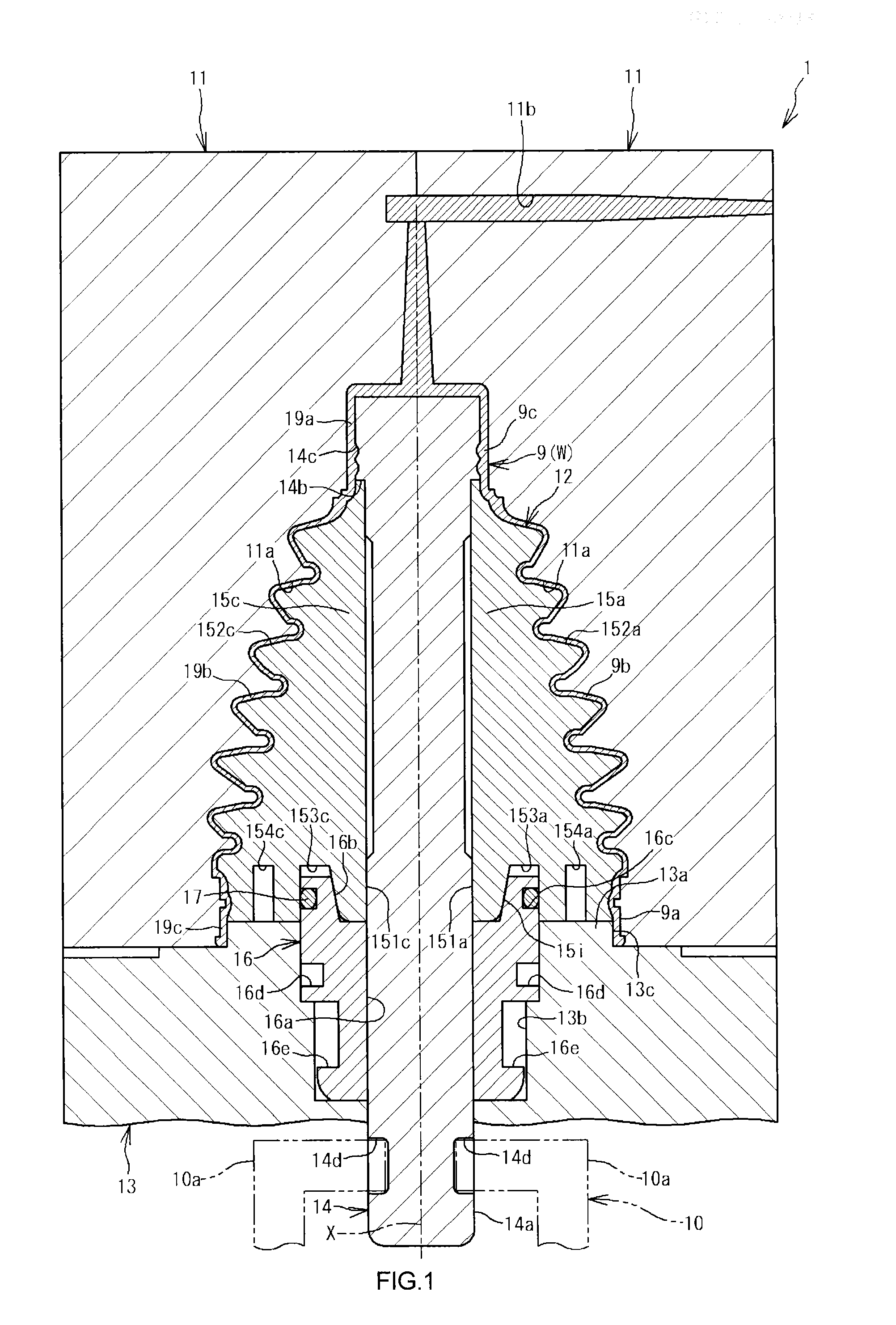
[0024]Next, preferable embodiments of the invention will be described with reference to the accompanying drawings. FIG. 1 is a sectional view showing a molding die used in a method of molding a boot for a constant velocity joint according to an embodiment of the invention. In FIG. 1, a molding die 1 is used for molding a boot 9 for a constant velocity joint by injection molding. The molding die 1 is constituted by a pair of right and left outer dies 11, an inner die 12, and a lower die 13. The inner die 12 is arranged inside the outer dies 11. The lower die 13 is arranged under the outer dies 11. The boot 9 for a constant velocity joint is constituted by a larger-diameter portion 9a and a smaller-diameter portion 9c that are formed in a cylindrical shape, and a bellows portion 9b. The bellows portion 9b connects the larger-diameter portion 9a and the smaller-diameter portion 9c.

[0025]The outer dies 11 are arranged on an upper surface of the lower die 13 to be movable in a horizonta...


PUM

PropertyMeasurementUnit
timeaaaaaaaaaa
timeaaaaaaaaaa
velocityaaaaaaaaaa

Abstract

An inner die of a molding die includes a core shaft, split dies radially arranged along an outer peripheral surface of the core shaft around an axis of the core shaft, which serves as a center, and a cylindrical set ring arranged below the split dies, the core shaft being inserted through the set ring. An annular engaging surface, which is a tapered surface whose diameter is gradually reduced downward, is formed in an inner peripheral side of an upper end portion of the set ring, and lower end portions of the respective split dies are introduced into, and engaged with the engaging surface. The molding die includes a pressing portion that presses downward upper end portions of the respective split dies introduced into the set ring, so as to move the lower end portions of the respective split dies toward the axis along the engaging surface.

Description

INCORPORATION BY REFERENCE[0001]The disclosure of Japanese Patent Application No. 2012-257532 Filed on Nov. 26, 2012 including the specification, drawings and abstract, is incorporated herein by reference in its entirety.BACKGROUND OF THE INVENTION[0002]1. Field of the Invention[0003]The present invention relates to a molding die for molding a boot for a constant velocity joint.[0004]2. Description of Related Art[0005]For example, in vehicles such as an automobile, constant velocity joints are used in order to transmit a rotation force to driving wheels that move upward and downward according to a road surface. A boot for a constant velocity joint made of synthetic resin is fitted to the constant velocity joint, in order to protect the constant velocity joint from external muddy water or dust and to retain lubricating grease supplied to the constant velocity joint. The boot for a constant velocity joint includes a cylindrical larger-diameter portion and a cylindrical smaller-diamete...

Claims


Application Information

Patent Timeline
Patent Type & Authority Applications(United States)
IPC IPC(8): B29C45/33
CPCB29C45/33B29C45/2624B29C45/4421B29C33/485B29L2031/703B29C45/332
Inventor UENO, HIROSHIHAMADA, KAZUKI
Owner JTEKT CORP
Why Eureka
Try Eureka