Multi-mode IFF receiver architecture

a receiver architecture and multi-mode technology, applied in the field of multi-mode radio frequency (rf) receiver architecture, can solve the problems of incompatibility with mode 5, spectrum applications which require a much larger receiver bandwidth, phase distortion, pulse fidelity,

Inactive Publication Date: 2005-04-26
BAE SYST INFORMATION & ELECTRONICS SYST INTERGRATION INC
View PDF6 Cites 22 Cited by
  • Summary
  • Abstract
  • Description
  • Claims
  • Application Information

AI Technical Summary

Benefits of technology

[0013]According to another aspect of the invention, the second IF channel includes a limiter coupled to an output of the wide band IF filter, and the wide band IF filter is configured to reject potentially interfering signals by an amount sufficient to prevent the limiter from being captured by the interfering signals.

Problems solved by technology

Specifically, since emitted MIDS signals use spread spectrum modulation, broadband noise generated by a MIDS transmitter may be within the passband of an IFF transponder receiver.
But certain performance parameters such as pulse fidelity, phase distortion, inter-symbol interference and receiver group delay have bene compromised, however.
And, while a narrow band receiver front end may allow Mark XII and Mode S interrogating signal waveforms to be detected reliably while rejecting MIDS signal interference, such an approach is incompatible with Mode 5 IFF spread spectrum applications which require a much larger receiver bandwidth for full processing gain.

Method used


Image

  • Multi-mode IFF receiver architecture
  • Multi-mode IFF receiver architecture
  • Multi-mode IFF receiver architecture

Examples


Embodiment Construction

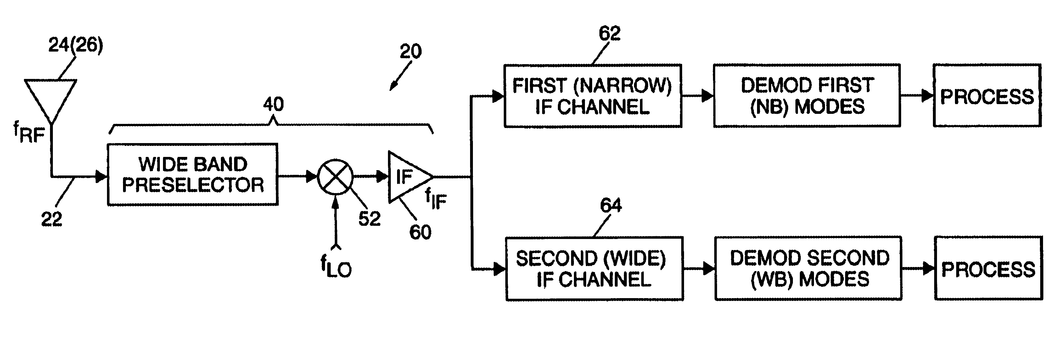
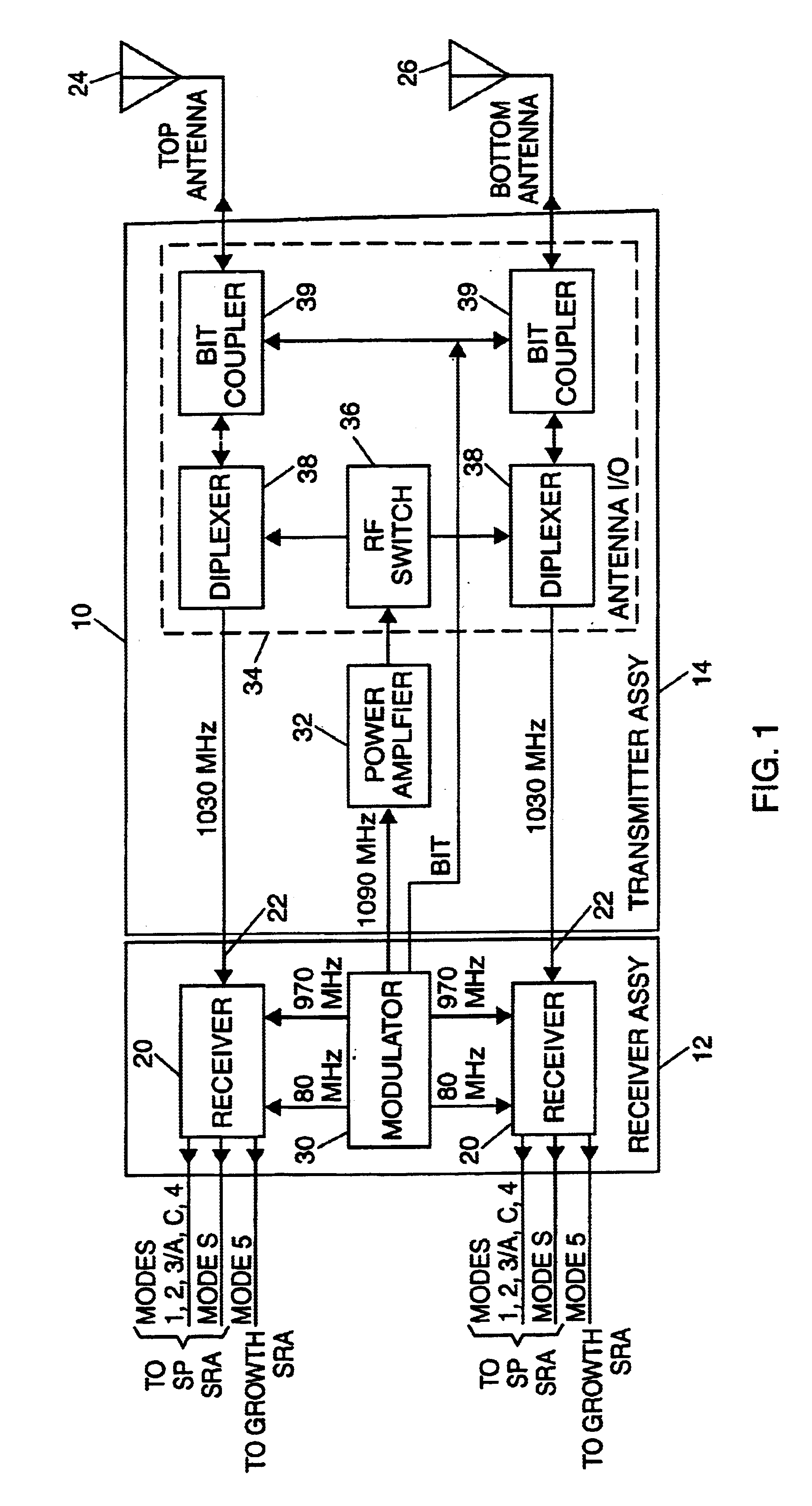
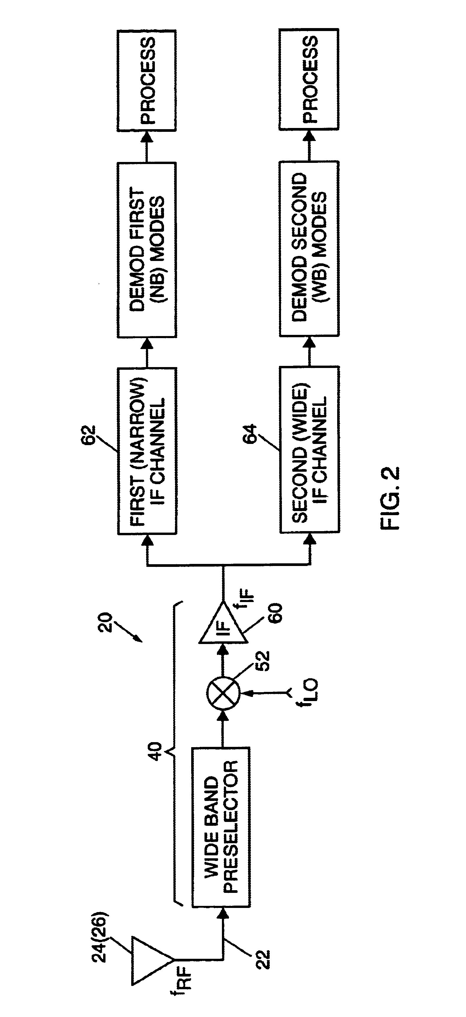
[0021]FIG. 1 is a functional block diagram of a transponder 10 including a receiver assembly 12 and a transmitter assembly 14. The receiver assembly 12 includes two substantially identical receivers 20, each with an input terminal 22 adapted for coupling to a separate receiving antenna 24 or 26 for diversity performance. For example, a top antenna 24 associated with one of the receivers, and a bottom antenna 28 associated with the other receiver, may be deployed at corresponding top and bottom positions on an aircraft body. Each receiver 20 is configured to respond, for example, to desired Mark XII SIF Modes 1, 2, 3 / A, C and Mode 4, as well as to desired Mode S and Mode 5 interrogating signal waveforms. An overall block diagram of one of the receivers 20 is given in FIG. 2.

[0022]The receiver assembly 12 also has a modulator 30, which provides frequency generation for each of the receivers, and waveform modulation for the transmitter assembly 14. The transmitter assembly 14 includes ...


PUM


Abstract

A transponder receiver for detecting different radio frequency (RF) interrogation mode signals having relatively wide and narrow bandwidths about a common RF center or carrier frequency. A front end stage of the receiver has a preselector with a wide band RF filter for passing both of the wide and the narrow bandwidth interrogation mode signals about the RF center frequency, and a mixer for converting signals from the preselector to frequencies within an intermediate frequency (IF) band. A first IF channel has a narrow band IF filter with a pass band sufficiently wide to pass first IF signals corresponding to the narrow bandwidth interrogation mode signals, but to reject signals corresponding to undesired interfering signals at frequencies near the narrow bandwidth interrogation mode signals. A second IF channel has a wide band IF filter with a pass band sufficiently wide to pass second IF signals corresponding to the desired wide bandwidth interrogation mode signals. The receiver may be incorporated in a transponder for operation in narrow IFF Modes 1-4, C and S, and in wide IFF Mode 5, with optimum performance in all modes.

Description

BACKGROUND OF THE INVENTION[0001]1. Field of the Invention[0002]This invention relates to a multi-mode radio frequency (RF) receiver architecture.[0003]2. Discussion of the Known Art[0004]The ability to distinguish reliably between friendly and hostile approaching aircraft, is extremely important. So-called identification-friend-from-foe (IFF) systems, e.g., the Mark X IFF system, employ a single interrogation frequency (1,030 MHz) and a single reply frequency (1,090 MHz) with a standard reply code. Three coded interrogations, designated Modes 1, 2 and 3 can be selected, wherein each interrogation has a pulse spacing of 3, 5 or 8 μsec corresponding in order to the selected mode.[0005]An airborne transponder replies with a single pulse for Modes 1 and 3, and a pulse-pair with 16 μsec spacing for Mode 2. A coder unit enables variable coded replies to be generated providing a Special Identity Feature (SIF), thus allowing a ground controller quickly to determine a particular aircraft's ...

Claims


Application Information

Patent Timeline
Patent Type & Authority Patents(United States)
IPC IPC(8): G01S13/76G01S13/00G01S7/285G01S13/78
CPCG01S7/285G01S13/767G01S13/781G01S13/765
Inventor CONIGLIONE, JOSEPH P.
Owner BAE SYST INFORMATION & ELECTRONICS SYST INTERGRATION INC
Why Eureka
Try Eureka