Supercharge Your Innovation With Domain-Expert AI Agents!

Universal charging cord with an illuminated socket end

a charging cord and socket end technology, applied in the direction of coupling device details, coupling device connection, transportation and packaging, etc., can solve the problems of difficult to see the connection port and difficult to see what they are writing

Inactive Publication Date: 2012-04-05
BURRELL IV JAMES W
View PDF5 Cites 25 Cited by
  • Summary
  • Abstract
  • Description
  • Claims
  • Application Information

AI Technical Summary

Benefits of technology

"The present invention provides methods and apparatuses for using a multi-functional charging cord or cigarette lighter charging cord to power and charge all devices. The charging cord includes a cable with at least two wires, a standard voltage or multi-voltage regulator cigarette lighter plug on one end for converting the supplied power voltage into the required DC voltage, and a socket with at least one illumination source facing outward or in the socket housing. The standard battery voltage for mobile device batteries is usually between 1.5V and 2.4V, while the voltage output of a cigarette lighter socket is usually between 1V and 12+volts. The multi-voltage regulator embodiment provides DC voltages ranging from 1V to 12+volts. The illumination source can be powered internally or by the connected device and can be powered by different types of plug tips or socket tips. The charging cord allows for easy replacement of either end with any type of powering or charging means. The invention allows for the powering or charging of any type of device using any type of power source or device."

Problems solved by technology

When connecting a charging cord to a device at night, it is difficult to see the connection port while inserting the plug into the device and the orientation of the plug end for insertion into the device.
At night, if a right-handed driver, when seated in the driver seat, uses the overhead light to illuminate the car interior while they are writing something, the right hand produces a shadow over what they are writing, making it difficult to see what they are writing.

Method used


Image

  • Universal charging cord with an illuminated socket end
  • Universal charging cord with an illuminated socket end
  • Universal charging cord with an illuminated socket end

Examples


Embodiment Construction

[0066]Wherever possible in the following description, like reference numerals will refer to like elements and parts, unless otherwise illustrated. It will be apparent to one skilled in the art that well known features have not been described in detail to avoid obscuring the multiple embodiments of the invention. Additional objects of the present invention will become apparent as the description proceeds.

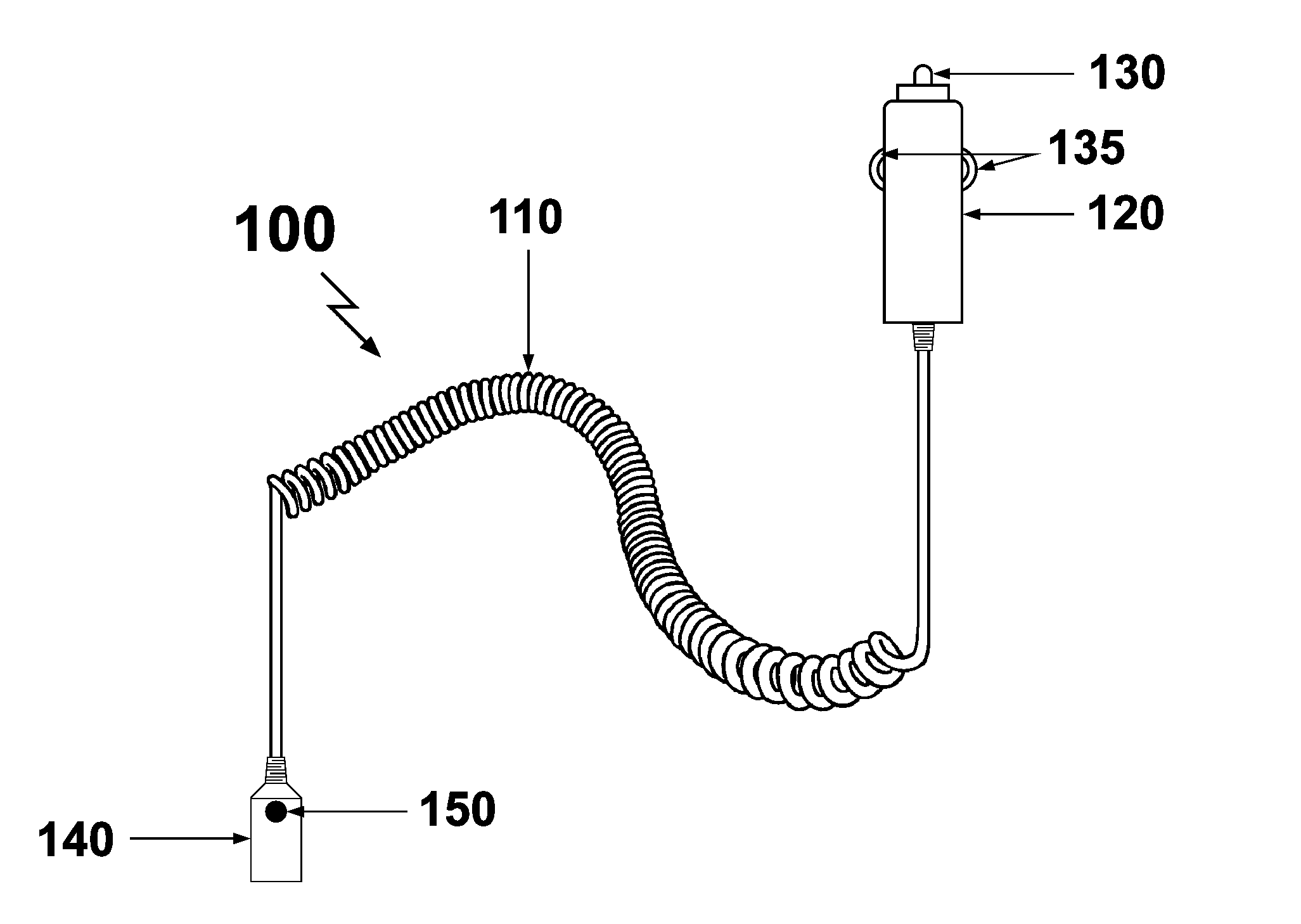
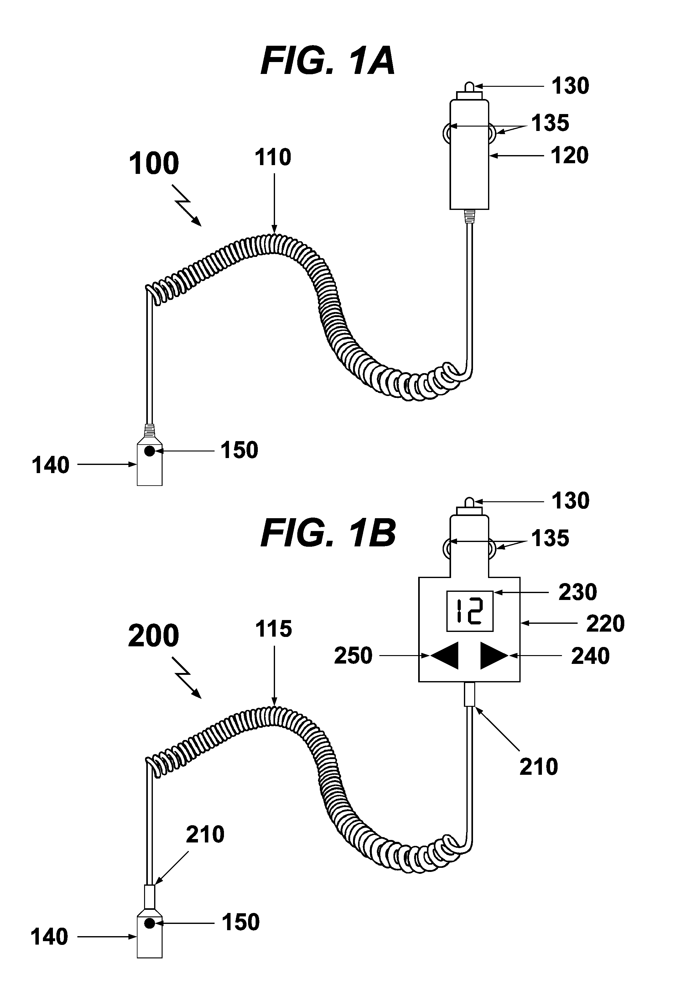
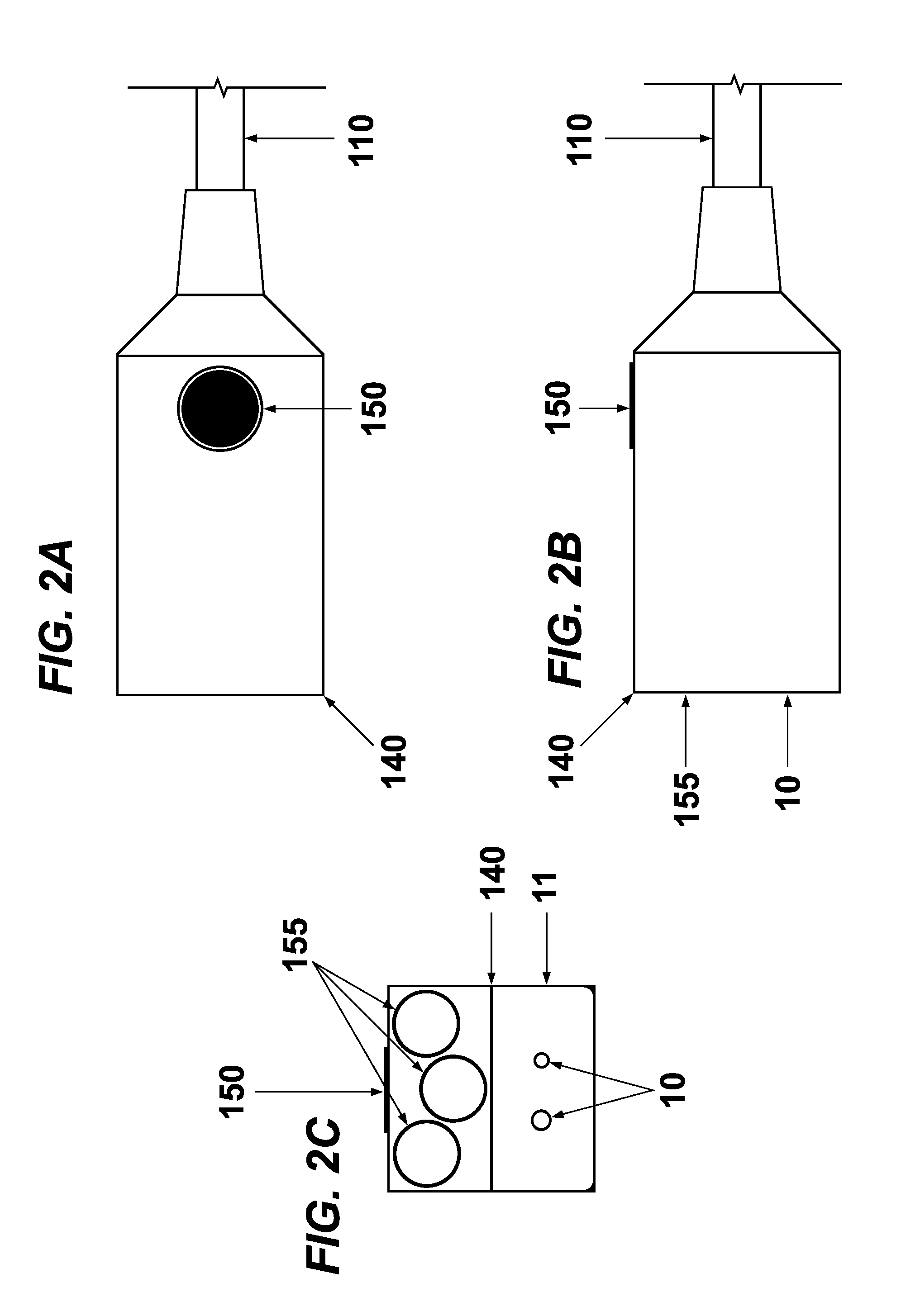
[0067]FIG. 1A illustrates an exemplary cigarette lighter charger 100 according to the present invention. The cigarette lighter charger 100 comprises a cable 110 with at least two wires for electrically connecting a cigarette lighter plug 120 with a specific DC voltage output comprising a first electricity contact tip 130 and second electricity contact springs 135 for insertion into a cigarette lighter socket power supply and an opposite outlet socket port 140 end with an illumination source 155 directionally located on or in the housing which can be turned on or off with a switch 150...


PUM


Abstract

A universal charger with an illuminated socket end is disclosed. The illumination source may be internally or externally powered from either end. Exchangeable charging plugs and sockets power and charge all mobile devices including: 12V DC to one of thirteen AC outlets, a secondary illumination source, a splitter socket plug, a male or female charging plug, a powered communications charging plug or socket, etc. A multi-voltage regulator with a voltage indicator provides exact voltages for specific devices. One of thirteen AC to DC charging adapters allows the charger to be plugged into any AC outlet in the world. A magnetic clip allows the illuminated socket end to be clipped on a visor or placed in any location for hands-free aiming of the illumination source. A cable with removable plug and socket ends allows multiple length charger cords, plug tips, plug sockets, DC to AC outlets, AC to DC adapters, etc.

Description

RELATED APPLICATION[0001]This application claims priority to and is a continuation in part of U.S. Provisional Patent Application No. 61 / 388,653, filed Oct. 1, 2010.FIELD OF THE INVENTION[0002]The present invention relates to portable chargers for mobile devices having a light source readily available, and more particularly to multi-functional portable chargers for powering and charging all devices using any and all types of DC or AC electrical sockets and plugs found throughout the world.BACKGROUND OF THE INVENTION[0003]Mobile charging cords are designed to be inserted in a cigarette lighter outlet.[0004]Cigarette lighter outlets provide a 12+ volt maximum, 15 amp power supply within a vehicle. 12V power fluctuates from 12.5V when not charging to around 14.5V when the alternator is charging and can drop to 5V-6V when the engine is started. DC to DC converters compensate for the fluctuations. Trucks use a 24V electrical system. Aircraft use a 28V electrical system. Most vehicles hav...

Claims


Application Information

Patent Timeline
Patent Type & Authority Applications(United States)
IPC IPC(8): H02J7/00
CPCH01R13/6675H02J7/0042H01R31/065H01R13/7175
Inventor BURRELL, IV, JAMES W.
Owner BURRELL IV JAMES W
Features
  • R&D
  • Intellectual Property
  • Life Sciences
  • Materials
  • Tech Scout
  • Unparalleled Data Quality
  • Higher Quality Content
  • 60% Fewer Hallucinations
Learn More