Dynamic graphical user interfaces for medical workstations

a workstation and dynamic technology, applied in the field of dynamic graphical user interfaces for medical workstations, can solve the problems of insufficiently presenting dynamic interfaces, difficulty in understanding concurrent visualization across different locations and orientations of workstation displays, and little progress in offering dynamic interfaces to provide contex

Active Publication Date: 2012-04-05
SIEMENS HEALTHCARE GMBH
View PDF6 Cites 42 Cited by
  • Summary
  • Abstract
  • Description
  • Claims
  • Application Information

AI Technical Summary

Problems solved by technology

In a medical imaging workstation, multiple views of the same dataset are often displayed simultaneously, but little progress has been made in terms of offering dynamic interfaces to provide context.
Although useful, concurrent visualization across different locations and orientations of a workstation display can sometimes be difficult for users to understand.
However, the problem still remains to adequately demonstrate to the user how an oblique plane relates to the rest of the data.

Method used


Image

  • Dynamic graphical user interfaces for medical workstations
  • Dynamic graphical user interfaces for medical workstations
  • Dynamic graphical user interfaces for medical workstations

Examples


Embodiment Construction

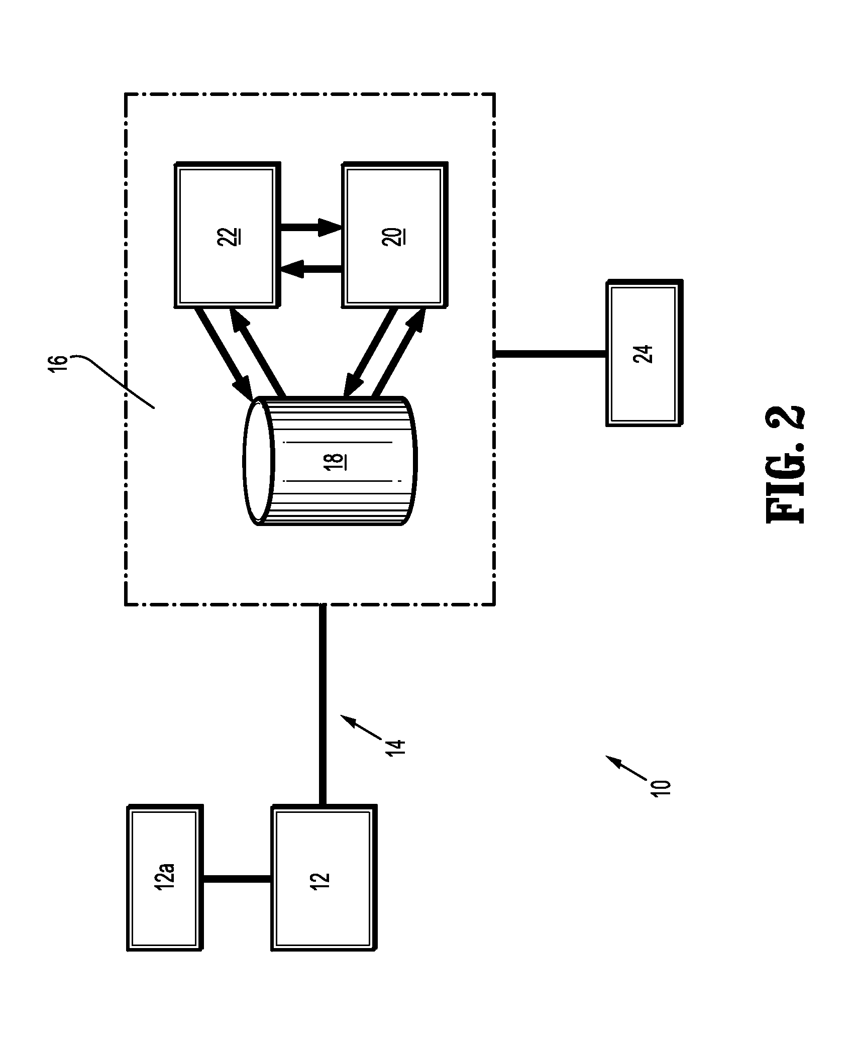
[0018]FIG. 2 is a block diagram of a medical imaging system 10 (simplified) that is operable in accordance with the present invention. The system 10 comprises a medical imaging scanner 12 that acquires image data of the anatomical region of interest of a patient under examination and, more particularly in this case, the airways of the patient. As noted above, the scanner 12 may use computed tomography (CT) imaging which has become one of the primary means to examine abnormalities of airways. However, the scanner 12 may use any other appropriate imaging modality to acquire 3D image data, for example, magnetic resonance, ultrasound, and nuclear medicine imaging. The scanner 12 may acquire raw image data from multiple scanned views of the anatomical region of interest, reconstruct the images, and produce an image volume. The image data signals may be in Digital Imaging and Communications in Medicine (DICOM) format. Other formats may also be used.

[0019]The imaging scanner 12 is operably...


PUM


Abstract

A dynamic method (100) to better depict context among the different views of an imaging visualization application used by a medical workstation.

Description

CROSS-REFERENCE TO RELATED APPLICATIONS[0001]This application claims the benefit of Provisional U.S. Patent Application Ser. No. 61 / 388,185 entitled, “Dynamic GUIs for Medical Workstations with Applications to the Airways”, filed in the name of Atilla Peter Kiraly, Benjamin L. Odry, and Carol L. Novak on Sep. 30, 2010, the disclosure of which is hereby incorporated by reference herein.FIELD OF INVENTION[0002]The present invention relates to medical imaging workstations. More particularly, the present invention relates to graphical user interfaces for medical workstations.BACKGROUND OF THE INVENTION[0003]The graphical user interfaces (GUIs) of modern computer systems are software programs that permit users to interact with the systems via graphical images on the system displays. They often depict spatial relationships between conceptual elements using graphical images, such as windows, menus, and dialogs with a dynamic interface. For example, a menu dynamically unfolds from a selecte...

Claims


Application Information

Patent Timeline
Patent Type & Authority Applications(United States)
IPC IPC(8): G09G5/377G06T15/00
CPCG09G2340/12G06T19/00G09G2380/08G06T2219/008A61B5/055A61B6/032A61B6/5241A61B8/5253G09G5/14
Inventor KIRALY, ATILLA PETERNOVAK, CAROL L.ODRY, BENJAMIN L.
Owner SIEMENS HEALTHCARE GMBH
Why Eureka
Try Eureka