Backlight module
- Summary
- Abstract
- Description
- Claims
- Application Information
AI Technical Summary
Benefits of technology
Problems solved by technology
Method used
Image

Examples
first embodiment
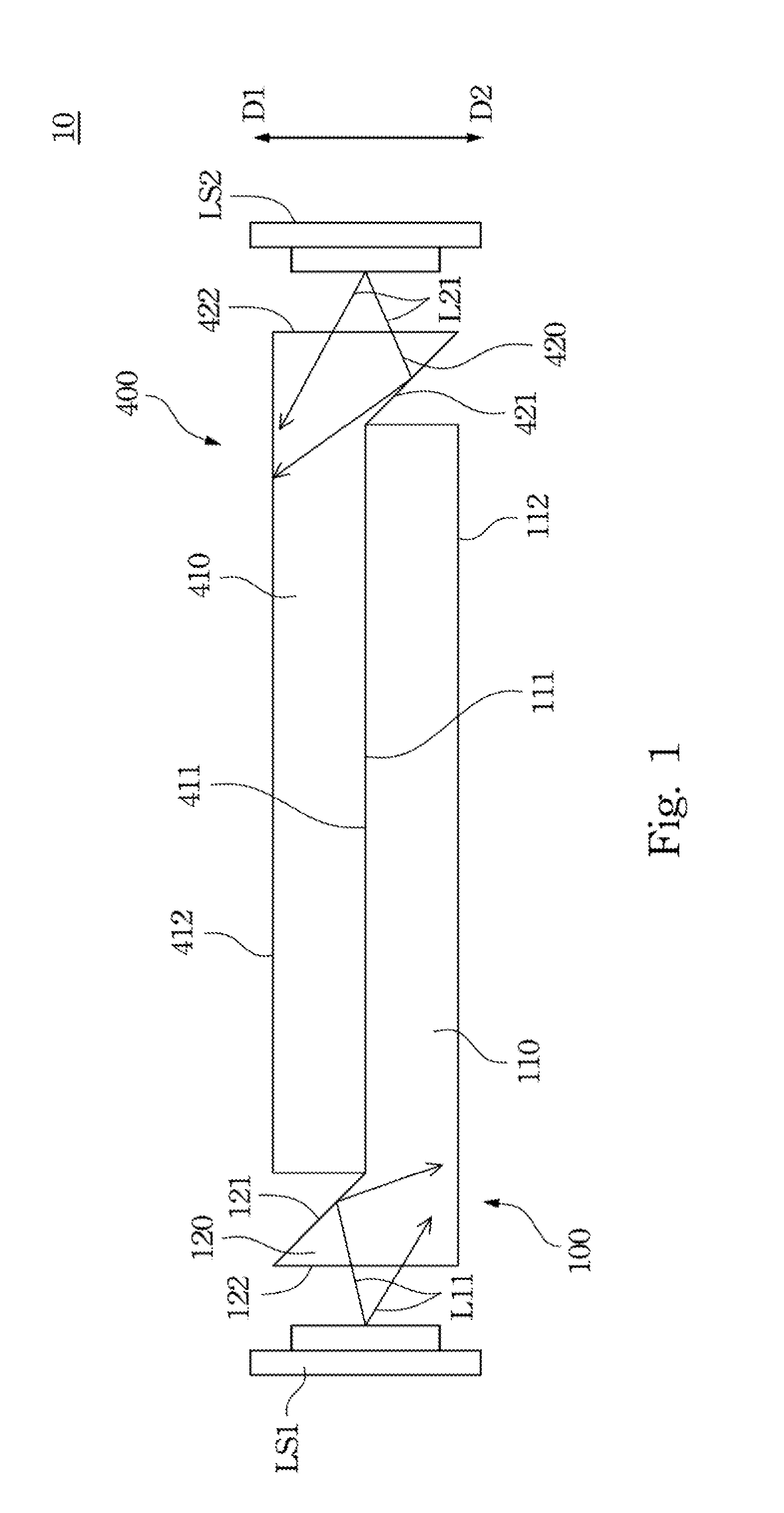
[0035]Refer to FIG. 1 in which FIG. 1 is a side view illustrating a backlight module 10 according to the present invention.
[0036]The first embodiment of the present invention provides a backlight module 10. The backlight module 10 includes a first light guide plate 100, a second light guide plate 400, a first light source LS1 and a second light source LS2. The first light guide plate 100 is substantially presented as an “L” shape, and includes a first plate body 110 and a first extending portion 120. The first plate body 110 is provided with a first inner surface 111 and a first outer surface 112 which are opposite with each other, and a number of lateral sides (shown in FIG. 1) surrounding the first inner surface 111 and the first outer surface 112 in which the area of each lateral side of the first light guide plate 100 is smaller than both the first inner surface 111 and the first outer surface 112, and each lateral side of the first light guide plate 100 is perpendicular to the ...
second embodiment
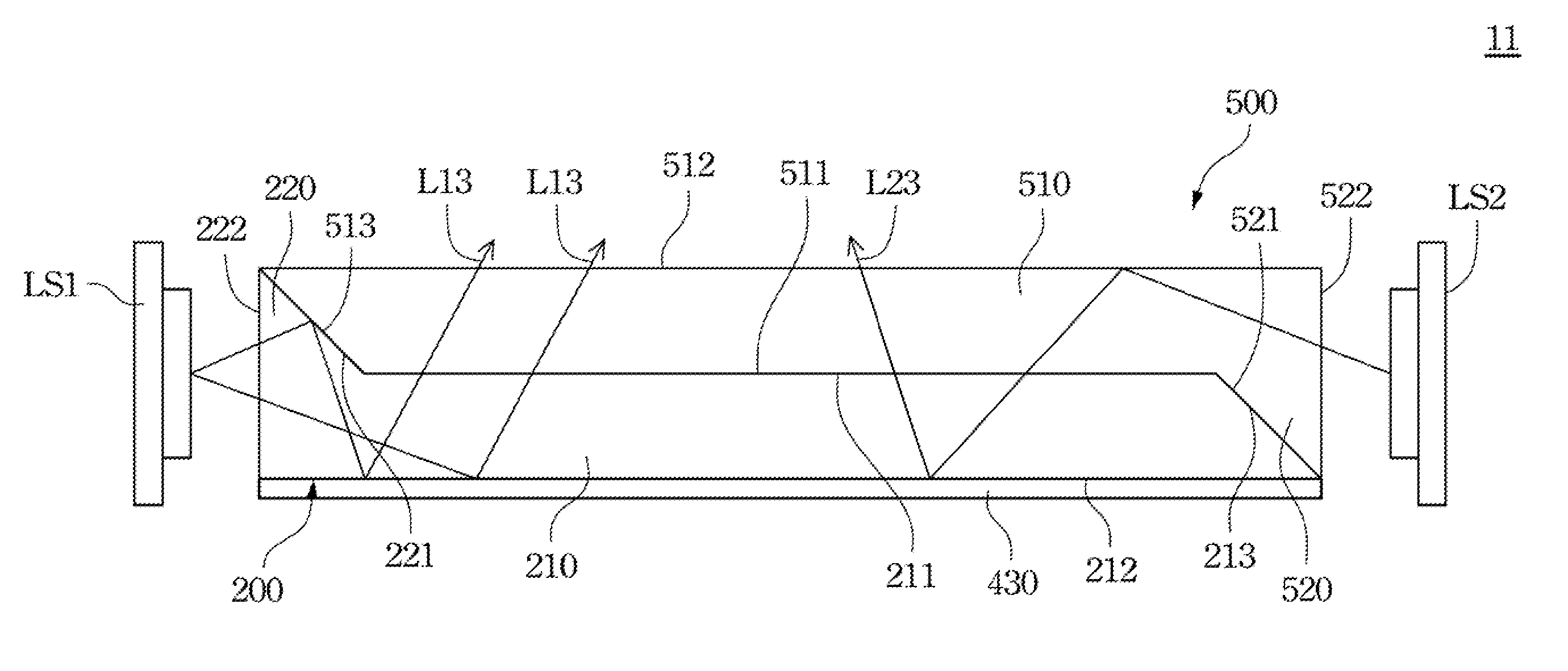
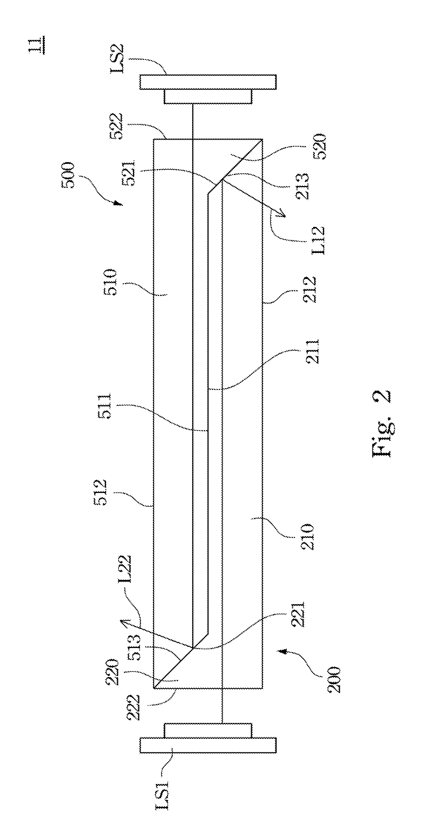
[0047]Refer to FIG. 2 in which FIG. 2 is a side view illustrating a backlight module 11 according to the present invention.
[0048]Based on the disclosure of the first embodiment in FIG. 1, besides the first plate body 210 and the first extended portion 220, the first light guide plate 200 of the backlight module 11 of the second embodiment further comprises a third reflective surface 213. The third reflective surface 213 is disposed on a lateral side of the first plate body 210 being far away from the first light incident surface 222, and neighboring to the second reflective surface 521, even contacting with the second reflective surface 521. Comparing to the first inner surface 211, the third reflective surface 213 is an inclined surface for relieving the light leakage on the first light guide plate 100. Furthermore, the third reflective surface 213 is formed with non-glossy surface (or rough surface) thereon for reflecting lights back in the first plate body 210.
[0049]Similarly, be...
third embodiment
[0087]The backlight module 12 of the present invention comprises a first light guide plate 300 and a second light guide plate 600, a first light source LS1, a second light source LS2 and a third light source LS3. The first light guide plate 300 is substantially presented as a “U” shape, comprises a first plate body 310, a first extending portion 320, and a third extending portion 330.
[0088]The first plate body 310 is provided with a first inner surface 311 and a first outer surface 312 which are opposite with each other, and a number of lateral sides (shown in FIG. 5A) surrounding the first inner surface 311 and the first outer surface 312 in which the area of each lateral side of the first light guide plate 300 is smaller than both the first inner surface 311 and the first outer surface 312, and each lateral side of the first light guide plate 300 is perpendicular to the first outer surface 312.
[0089]The first extending portion 320 is disposed on an edge of the first inner surface ...
PUM
 Abstract
Description
Claims
Application Information
 - R&D
- Intellectual Property
- Life Sciences
- Materials
- Tech Scout
- Unparalleled Data Quality
- Higher Quality Content
- 60% Fewer Hallucinations
Browse by: Latest US Patents, China's latest patents, Technical Efficacy Thesaurus, Application Domain, Technology Topic, Popular Technical Reports.
© 2025 PatSnap. All rights reserved.Legal|Privacy policy|Modern Slavery Act Transparency Statement|Sitemap|About US| Contact US: help@patsnap.com