Eureka AIR delivers breakthrough ideas for toughest innovation challenges, trusted by R&D personnel around the world.

System and method for governing a speed of an autonomous vehicle

Active Publication Date: 2012-04-05
DEERE & CO
View PDF10 Cites 172 Cited by
  • Summary
  • Abstract
  • Description
  • Claims
  • Application Information

AI Technical Summary

Problems solved by technology

However, many environmental conditions may exist that will retard or reduce the effective range of these perception systems.
For instance, cameras and other types of optical sensors may not be able to penetrate obscurants such as dust, smoke, and fog.
In addition, topographical features of the terrain within the operating environment may also make it impossible for the perception systems to make observations out to their nominal maximum range.

Method used


Image

  • System and method for governing a speed of an autonomous vehicle
  • System and method for governing a speed of an autonomous vehicle
  • System and method for governing a speed of an autonomous vehicle

Examples


Embodiment Construction

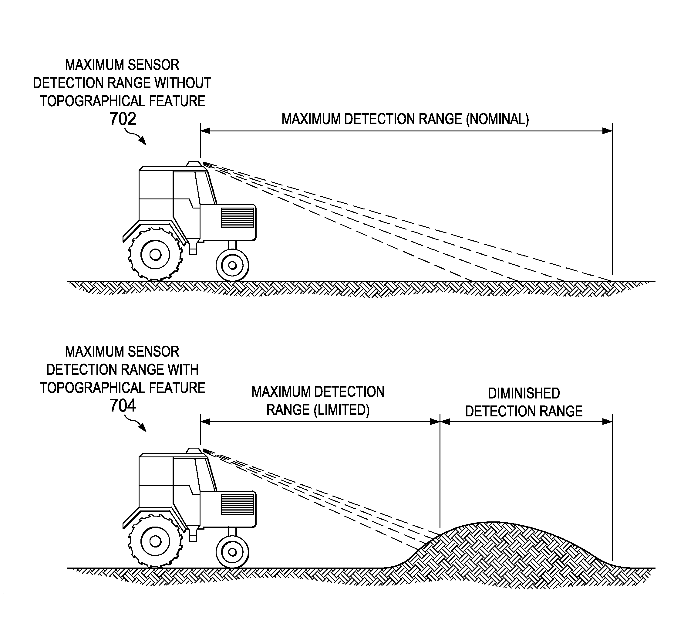
[0016]Illustrative embodiments of the present invention provide systems and methods for governing a maximum speed of an autonomous or semi-autonomous vehicle when environmental and / or topographical conditions reduce a maximum effective detection range of the vehicle's sensor system. A machine controller associated with the vehicle determines a location within an operating environment of the vehicle where discontinuity exists between currently generated laser data and previously generated laser data for the operating environment. The machine controller then selects image data that corresponds to the location where the discontinuity exists between the currently generated laser data and the previously generated laser data for the operating environment. In addition, the machine controller determines whether a non-motion blur score for the selected image data is above a predetermined threshold value. In response to determining that the non-motion blur score for the selected image data is...


PUM


Abstract

A method of adjusting a speed of a mobile machine is provided. Image data of a location is collected where currently generated sensor data and previously generated sensor data indicate a discontinuity in sensor data. The image data is analyzed to determine if a non-motion blur score for the image data is above a threshold value. Then, a speed of the mobile machine is adjusted based on a determination that the non-motion blur score is above the threshold value.

Description

FIELD OF THE INVENTION[0001]The present invention relates generally to a mobile machine system and more particularly to a method and system for governing a maximum speed of an autonomous or semi-autonomous vehicle.BACKGROUND OF THE INVENTION[0002]Perception systems for safeguarding and localization of autonomous and semi-autonomous vehicles may utilize many different sensing modalities, such as, for example, laser devices, color cameras, thermal cameras, ultrasonic devices, and radar devices, to detect obstacles and localize the vehicles in their operating environment. However, many environmental conditions may exist that will retard or reduce the effective range of these perception systems. For instance, cameras and other types of optical sensors may not be able to penetrate obscurants such as dust, smoke, and fog. In addition, topographical features of the terrain within the operating environment may also make it impossible for the perception systems to make observations out to th...

Claims


Application Information

Patent Timeline
IPC IPC(8): B60W30/00G06K9/00
CPCG05D1/0223G05D1/024G05D1/0242G05D1/0246G05D2201/0202G05D1/0274G05D1/0278G05D2201/0201G05D1/0257
Inventor BONEFAS, ZACHARY THOMASANDERSON, NOEL WAYNE
Owner DEERE & CO
Why Eureka
Eureka Blog
Learn More