Breathing assistance device with linear actuated gas regulating valve

a technology of gas regulating valve and breathing assistance device, which is applied in the direction of valve operating means/releasing devices, magnets, magnetic bodies, etc., can solve the problems of increasing the work of breathing for the patient, increasing the complexity of the controller, and high breathing resistan

Active Publication Date: 2012-04-12
RESMED LTD
View PDF13 Cites 18 Cited by
  • Summary
  • Abstract
  • Description
  • Claims
  • Application Information

AI Technical Summary

Benefits of technology

[0030]Another aspect of the invention involves a breathing assistance device that includes a gas supply, a gas supply line coupled to the gas supply, a patient interface, a pressure sensor that senses a pressure within the patient interface, and a gas regulating valve coupled between the gas supply line and the patient interface. The gas regulating valve includes a movable obstruction member that moves between a closed position at which the gas regulating valve couples the gas supply line to the patient interface and an open position at which the gas regulating valve couples the patient interface to the atmosphere. the breathing assistance device also includes a controller that is coupled to the pressure sensor and the gas regulating valve. The controller sends a control signal to the gas regulating valve that controls a degree to which the obstruction member moves from the open position toward the closed position. The controller calculates an expiratory flow of the patient when the patient is exhaling based upon a pressure within the patient interface, as sensed by the pressure sensor, and a value of the control signal sent to the gas regulating valve.
[0031]Another aspect of the invention involves a method of calculating a patient's expiratory flow when the patient is using a breathing assistance device that includes a patient interface that is coupled to a gas regulating valve, and wherein a control signal is applied to the gas regulating valve to control a flow through gas regulating valve. The method includes determining a pressure difference between a pressure within the patient interface and atmospheric pressure while the patient is expiring, determining a value of the control signal applied to the gas regulating valve while the patient is expiring, and calculating the patient's expiratory flow based on the determined pressure difference and the determined value of the control signal.

Problems solved by technology

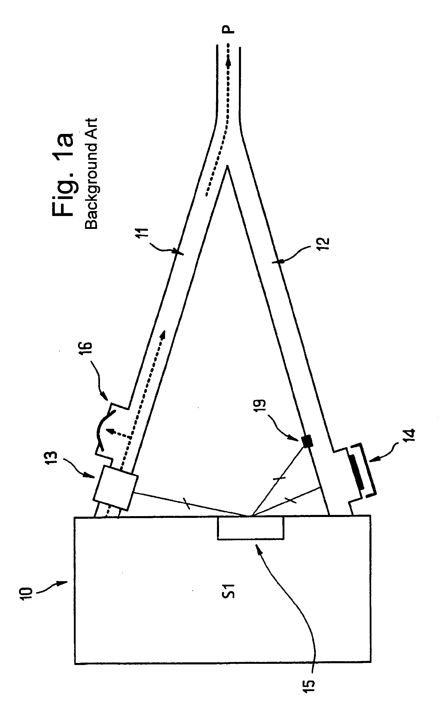
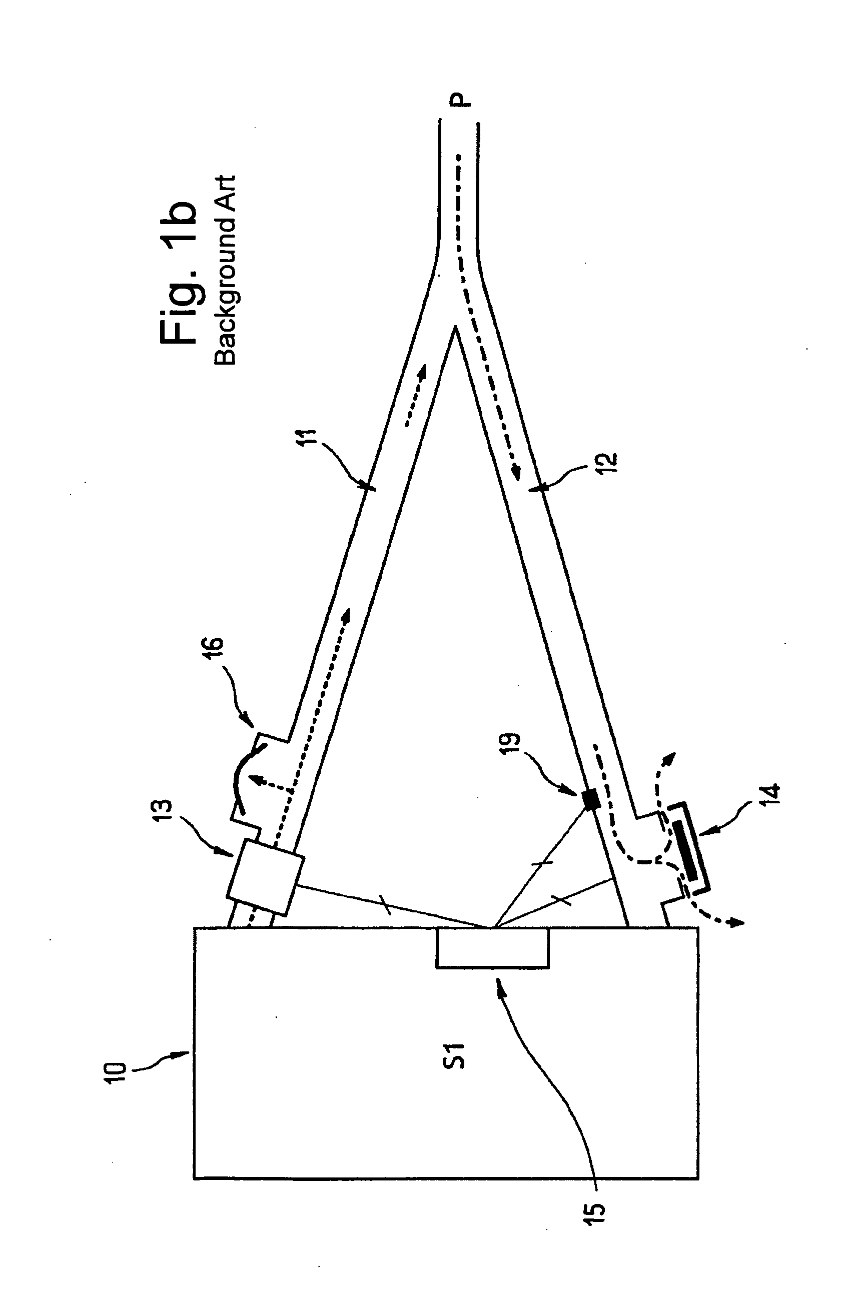
This configuration results in a high breathing resistance, which increases the work of breathing for the patient.
This increases the complexity of the controller 25 of the respirator.
In some respiratory modes, the expiratory valve 22 has to be operated as much as possible in real time, which is quite difficult in such expiratory valves because of the pneumatic inertias which are associated with them.
The requirement for such large diameter ducts is an obstacle to miniaturization of the device, particularly the breathing circuit.
And here again, such large duct diameters is an obstacle to miniaturization.

Method used


Image

  • Breathing assistance device with linear actuated gas regulating valve
  • Breathing assistance device with linear actuated gas regulating valve
  • Breathing assistance device with linear actuated gas regulating valve

Examples


Embodiment Construction

[0054]The following description is provided in relation to several embodiments which may share common characteristics and features. It is to be understood that one or more features of any one embodiment may be combinable with one or more features of the other embodiments. In addition, any single feature or combination of features in any of the embodiments may constitute additional embodiments.

[0055]In this specification, the word “comprising” is to be understood in its “open” sense, that is, in the sense of “including,” and thus not limited to its “closed” sense, that is the sense of “consisting only of.” A corresponding meaning is to be attributed to the corresponding words “comprise”, “comprised” and “comprises” where they appear.

[0056]The term “air” will be taken to include breathable gases, for example air with supplemental oxygen. It is also acknowledged that the blowers described herein may be designed to pump fluids other than air.

General Structure of Respirator and Breathing...


PUM

PropertyMeasurementUnit
pressure lossaaaaaaaaaa
diameteraaaaaaaaaa
diameteraaaaaaaaaa

Abstract

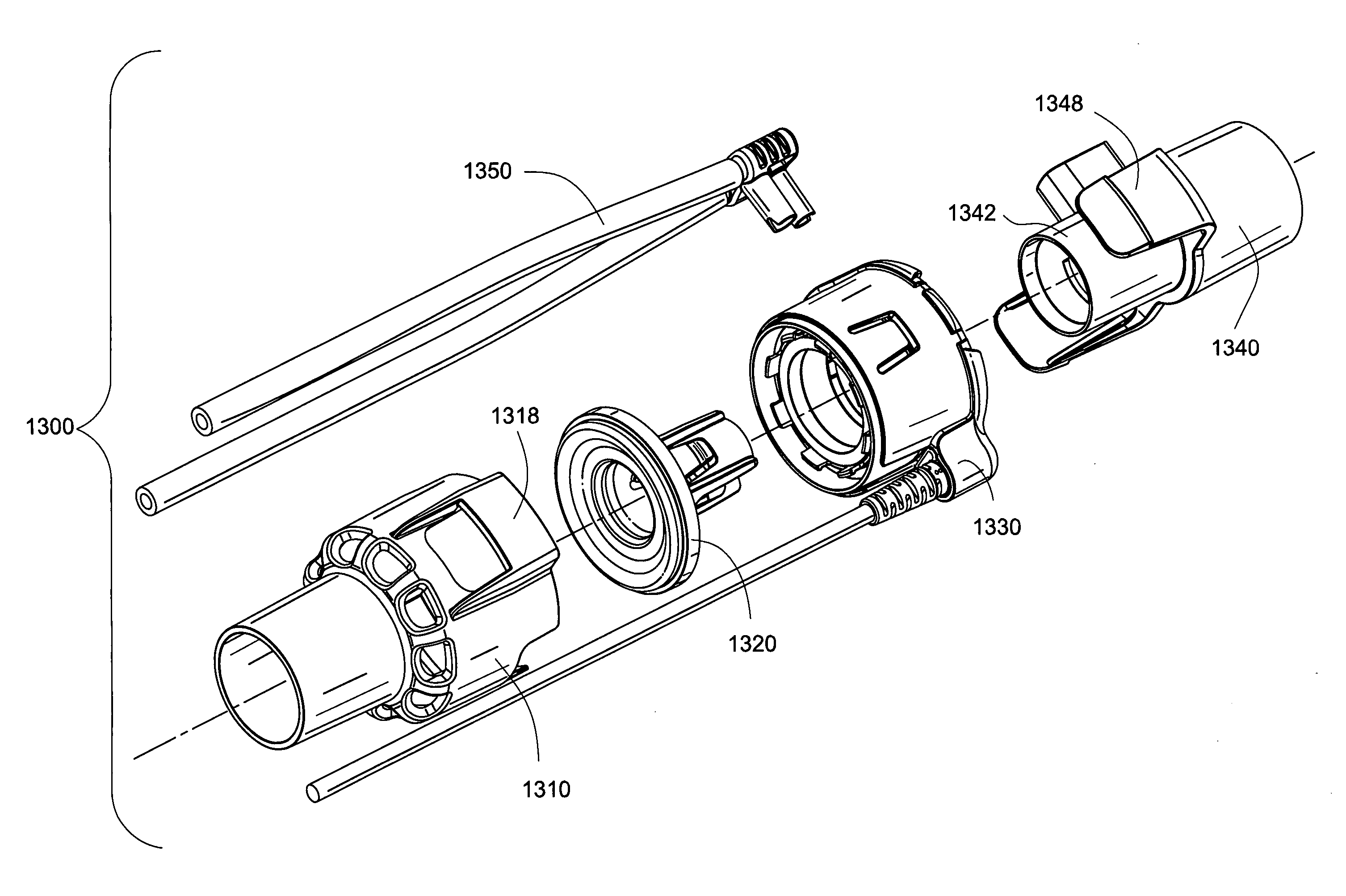
A breathing assistance device includes a gas regulating valve (1300). The gas regulating valve is operated by a linear actuator (1330). The linear actuator may include a movable member that moves an obstruction member between an open position and a closed position. The linear actuator is isolated from a gas flow path through the valve.

Description

CROSS REFERENCE TO RELATED APPLICATIONS[0001]This application claims the benefits of U.S. Provisional Patent Application Ser. No. 61 / 185,250, filed Jun. 9, 2009, the entire contents of which are incorporated herein by reference.FIELD OF THE INVENTION[0002]The present invention relates to a breathing assistance device, and more specifically, to a linear actuator that is used in a gas regulating valve of a breathing assistance device.BACKGROUND OF THE INVENTION[0003]A variety of breathing assistance devices, which we will also generally refer to as “respirators” in this text, are available today. These respirators are equipped with a source of respiratory pressurized gas. They are generally referred to as “autonomous” because an external pressurized gas feeding is not required to operate them. These devices provide the patient, at each inspiration, with a respiratory gas (typically ambient air to which a complementary gas such as oxygen can be added).[0004]Different types of respirato...

Claims


Application Information

Patent Timeline
Patent Type & Authority Applications(United States)
IPC IPC(8): A61M16/20B21K1/20H01F41/00F16K31/02
CPCA61M16/0066Y10T29/49412A61M16/12A61M16/16A61M16/20A61M39/22A61M2016/0027A61M2016/0036A61M2016/0042A61M2202/0208A61M2205/8206A61M2209/06F16K31/0651F16K31/0693F16K31/082F16K31/084H01F5/02H02K5/225H02K7/14H02K33/18A61M16/0006A61M16/1095A61M16/204A61M16/205A61M16/206A61M16/209Y10T29/4902A61M16/06A61M16/0866H01F5/04H01F7/066
Inventor CHALVIGNAC, PHILIPPE AUGUSTEWU, NAN HAITAYLOR, KENJUDSON, DANIEL ROBERTKLASEK, PAUL JANBLUNSDEN, CHRISTOPHER KINGSLEY
Owner RESMED LTD
Why Eureka
Try Eureka