Systems and methods for controlling the temperature of a room based on occupancy

a technology of occupancy and temperature control, applied in the field of automatic environment control system operation, can solve the problems of wasting energy, increasing the utility bill of the hotel, heating and cooling these unoccupied rooms is not only a waste of energy, but also of money, so as to reduce energy consumption

Inactive Publication Date: 2012-04-12
ENERGY EYE
View PDF0 Cites 247 Cited by
  • Summary
  • Abstract
  • Description
  • Claims
  • Application Information

AI Technical Summary

Benefits of technology

[0009]Systems and methods for controlling the temperature of a room using an environment control system are described herein. Improved techniques for determination of room occupancy status are provided. The environment control system can be configured to operate in an energy saving mode while the room in unoccupied. The energy saving mode can reduce energy consumption by controlling the run time of a heating and cooling system, e.g., a HVAC system based on both temperature and by controlling the duty run-time of the system.

Problems solved by technology

Rising energy costs have driven manufacturers to make an effort to make these systems more energy efficient; however, even the most energy efficient HVAC systems can still waste energy by heating or cooling unoccupied spaces within a building.
Heating and cooling these unoccupied rooms is not only a waste of energy, but also of money.
Heating and cooling unoccupied areas of hotel can significantly increase the hotel's utility bills.
Accordingly, it can be inefficient and costly to heat or cool the upstairs during the day and the downstairs at night.
During the day, many offices are likely to be occupied, while on weekends or during evenings, much of the building is likely to be vacant.
Often building owners or managers will simply turn off the HVAC services to the building during low occupancy periods; however, this leaves anyone occupying the building during these periods without HVAC services, which can result in a stuffy and / or uncomfortably hot or cold working environment.
Furthermore, this all or nothing approach does not take into account portions of the building that can remain unoccupied even during the peak occupancy hours (e.g., vacant offices).
Conventional HVAC systems do not provide the ability to limit HVAC services to occupied portions of the building.
However, these conventional approaches must sacrifice either energy efficiency or occupant comfort.
While this approach can result in significant energy savings by limiting or stopping HVAC services to unoccupied rooms, the temperatures of the room can become extremely uncomfortable for occupants entering the previously unoccupied room.
Furthermore, occupants returning to a room that is too hot may adjust the HVAC system to a much lower setpoint in order to more quickly bring the temperature of the room down to a comfortable range, which can sacrifice much of the energy savings provided by shutting down the HVAC system while the room was unoccupied.
Another problem with conventional techniques for reducing the energy consumption of a HVAC system is the inability of such systems to accurately determine whether a particular room or area is occupied.

Method used


Image

  • Systems and methods for controlling the temperature of a room based on occupancy
  • Systems and methods for controlling the temperature of a room based on occupancy
  • Systems and methods for controlling the temperature of a room based on occupancy

Examples


Embodiment Construction

.”

BRIEF DESCRIPTION OF THE DRAWINGS

[0014]Features, aspects, and embodiments are described in conjunction with the attached drawings, in which:

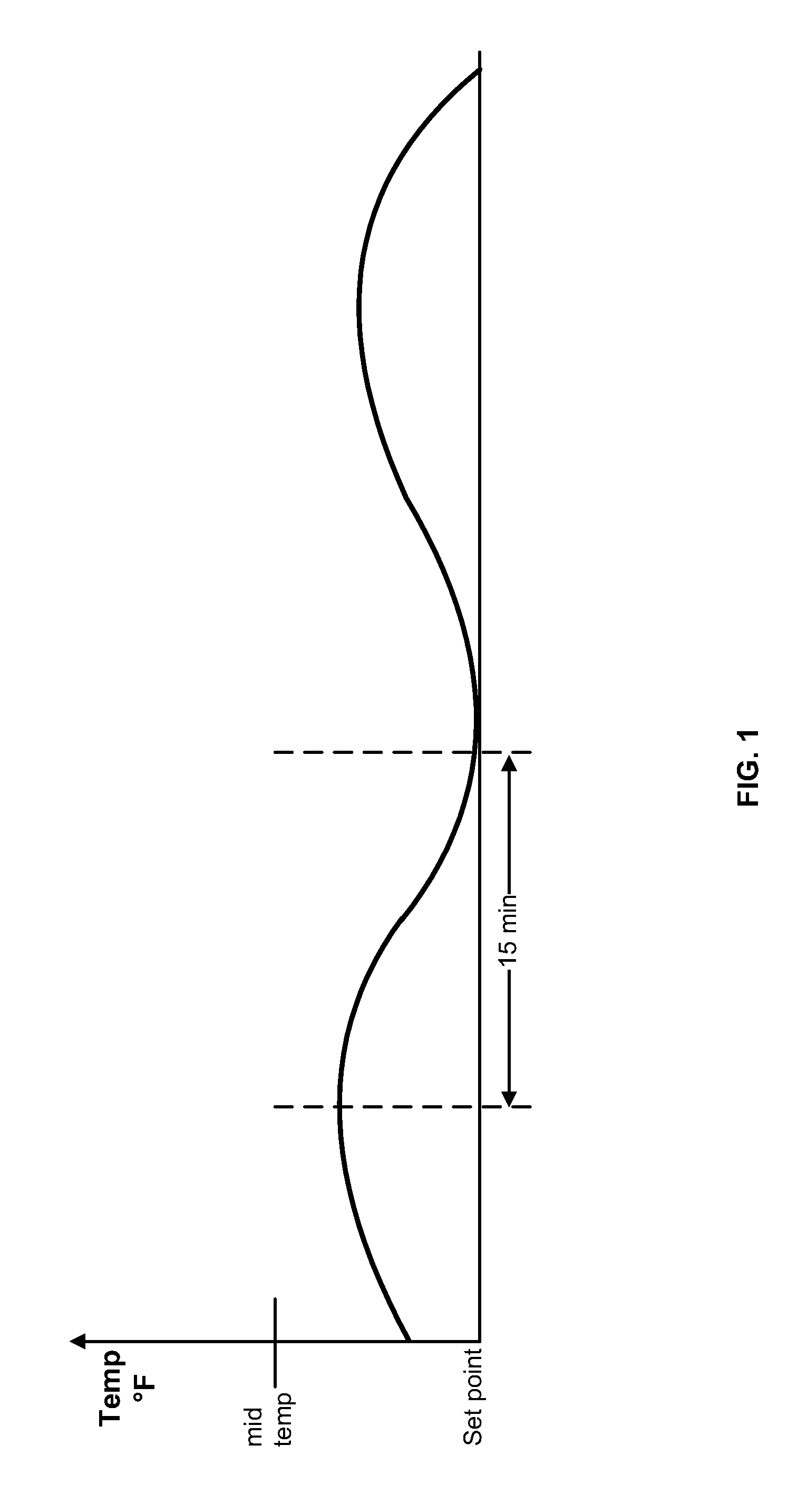
[0015]FIG. 1 is a plot of the temperatures in a room over time using a conventional environment control system to maintain the temperature of the room;

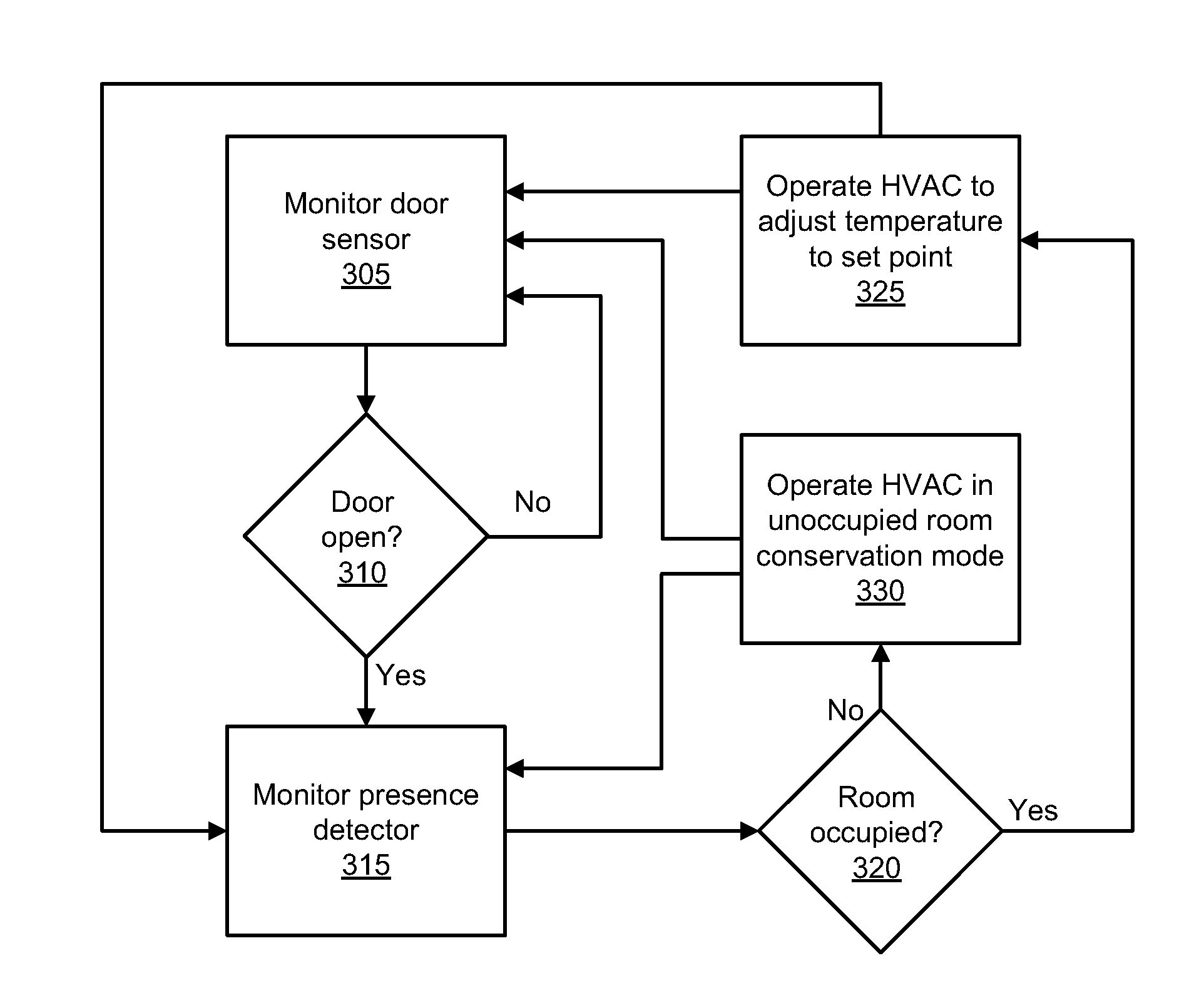
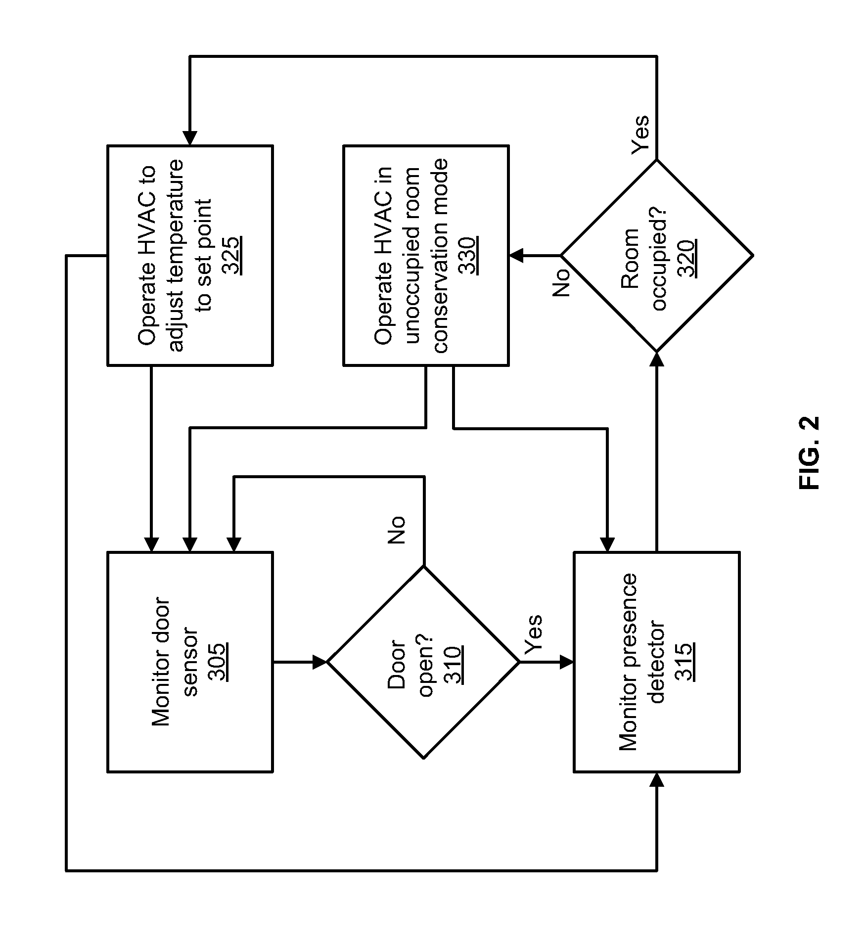
[0016]FIG. 2 is a flow chart illustrating an example process for operating an environment control system, such as that illustrated in FIG. 5, in accordance with an embodiment;

[0017]FIG. 3 is a flow chart illustrating an example process for operating an environment control system in a power saving mode according to one embodiment;

[0018]FIG. 4 is an example graph of the temperature versus time when implementing the process of FIG. 3; and

[0019]FIG. 5 is a diagram illustrating an example environment control system in accordance with one embodiment.

DETAILED DESCRIPTION

[0020]The following detailed description is directed to certain specific embodiments. However, it will be understood that these embodi...


PUM


Abstract

An environment control system for controlling the temperature in a room, the system comprises a heating and cooling system; a thermostat for monitoring the temperature within a room and controlling the heating and cooling system; a motion sensor for detecting whether a door or window to the room has been opened; a presence detector for detecting whether the room is currently occupied; and a control system in communication with the thermostat, the motion sensor, and the presence detector, the control system being configured to control the room's temperature via the thermostat based at least in part on signals received from the thermostat, the motion detector and the presence detector, the control system being configured to cause the heating and cooling system to operate in a power savings mode when the room is unoccupied based on a series of time cycles during which the heating and cooling system is turned on or off as dictated by a plurality of temperature thresholds.

Description

BACKGROUND[0001]1. Technical Field[0002]The embodiments described herein are related to automated environment control system operation and more particularly, to systems and methods for controlling the temperature of the room based on occupancy.[0003]2. Related Art[0004]Heating, ventilating, and air conditioning (HVAC) systems provide control over the indoor environment of buildings through heating, cooling, and air circulation. Rising energy costs have driven manufacturers to make an effort to make these systems more energy efficient; however, even the most energy efficient HVAC systems can still waste energy by heating or cooling unoccupied spaces within a building. For example, hotels can have numerous unoccupied guest rooms. Heating and cooling these unoccupied rooms is not only a waste of energy, but also of money. Heating and cooling unoccupied areas of hotel can significantly increase the hotel's utility bills. Heating and cooling of unoccupied areas of residential properties ...

Claims


Application Information

Patent Timeline
Patent Type & Authority Applications(United States)
IPC IPC(8): G05D23/19F24F11/76
CPCF24F11/0009F24F2011/0064F24F2011/0056F24F11/0034F24F11/30F24F2120/10F24F2140/40F24F11/65F24F2120/00F24F11/46F24F11/63F24F11/56G05D23/00
Inventor KOPP, PHILLIP M.
Owner ENERGY EYE
Why Eureka
Try Eureka