Gravity energy storage and generating device

a gravity energy storage and generating device technology, applied in the direction of winding mechanism, hoisting equipment, etc., can solve the problems of vacuum created, and achieve the effect of softening the fall of the piston

Inactive Publication Date: 2012-04-12
DAYA ARVIND A
View PDF8 Cites 10 Cited by
  • Summary
  • Abstract
  • Description
  • Claims
  • Application Information

AI Technical Summary

Benefits of technology

[0004]The main object of the invention is to provide improved mechanical energy storage and release device comprising of the wound and weight as energy storing elements. Energy storage device installed in the ground or above where gravity plays a vital role in generating and storing, a large concrete piston mass that fits in a long cylinder as required. Both end of the concrete piston is sealed with two rubber seal ring on the top of the said piston and the bottom of concrete piston. The cylinders top and the bottom is completely sealed (air tight). The piston's resting point or starting point is at the bottom of the cylinder. At the bottom of the cylinder below the concrete piston re

Problems solved by technology

Thirdly the vacuum that is created while the seal

Method used


Image

  • Gravity energy storage and generating device
  • Gravity energy storage and generating device
  • Gravity energy storage and generating device

Examples


Embodiment Construction

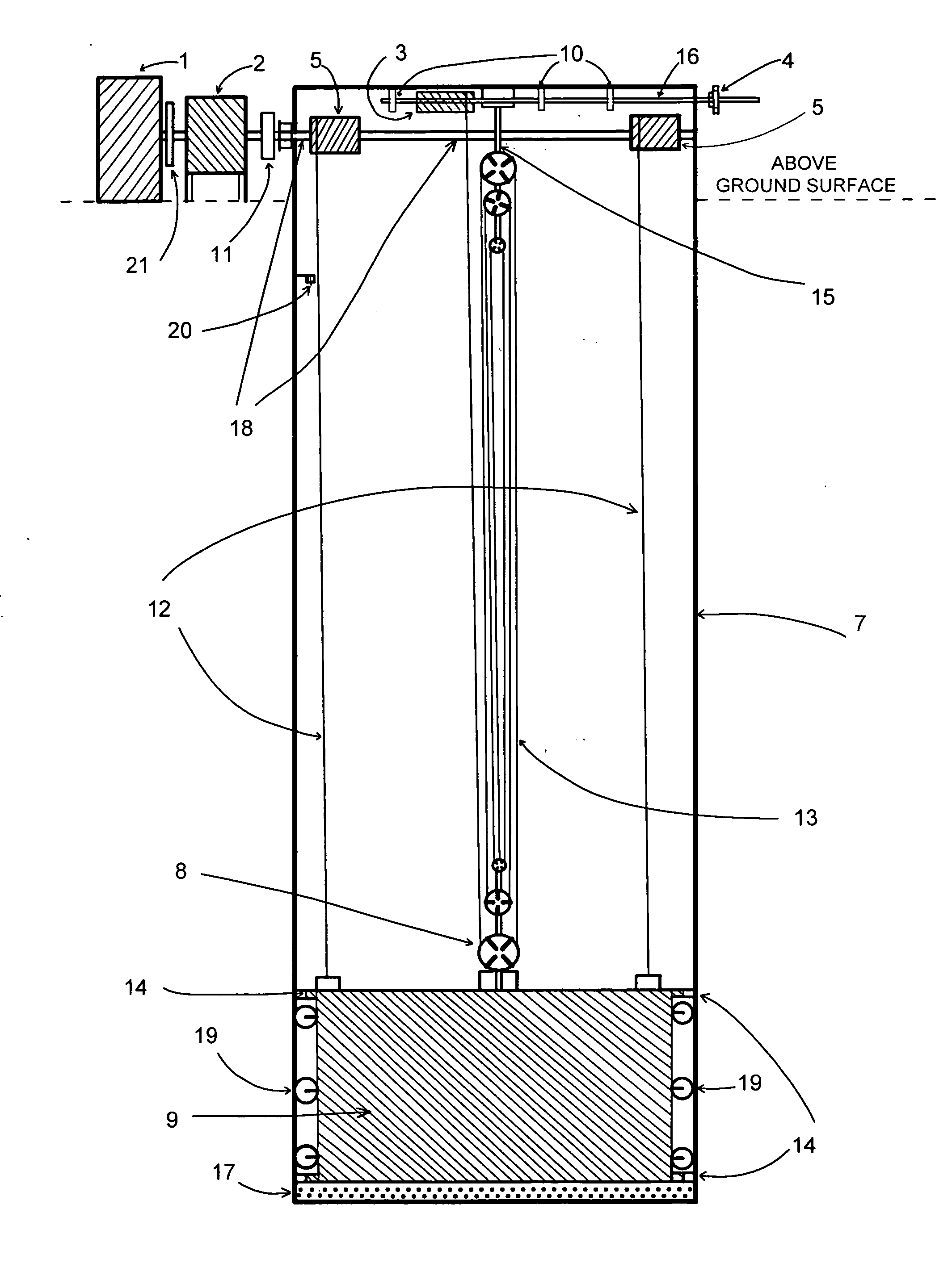
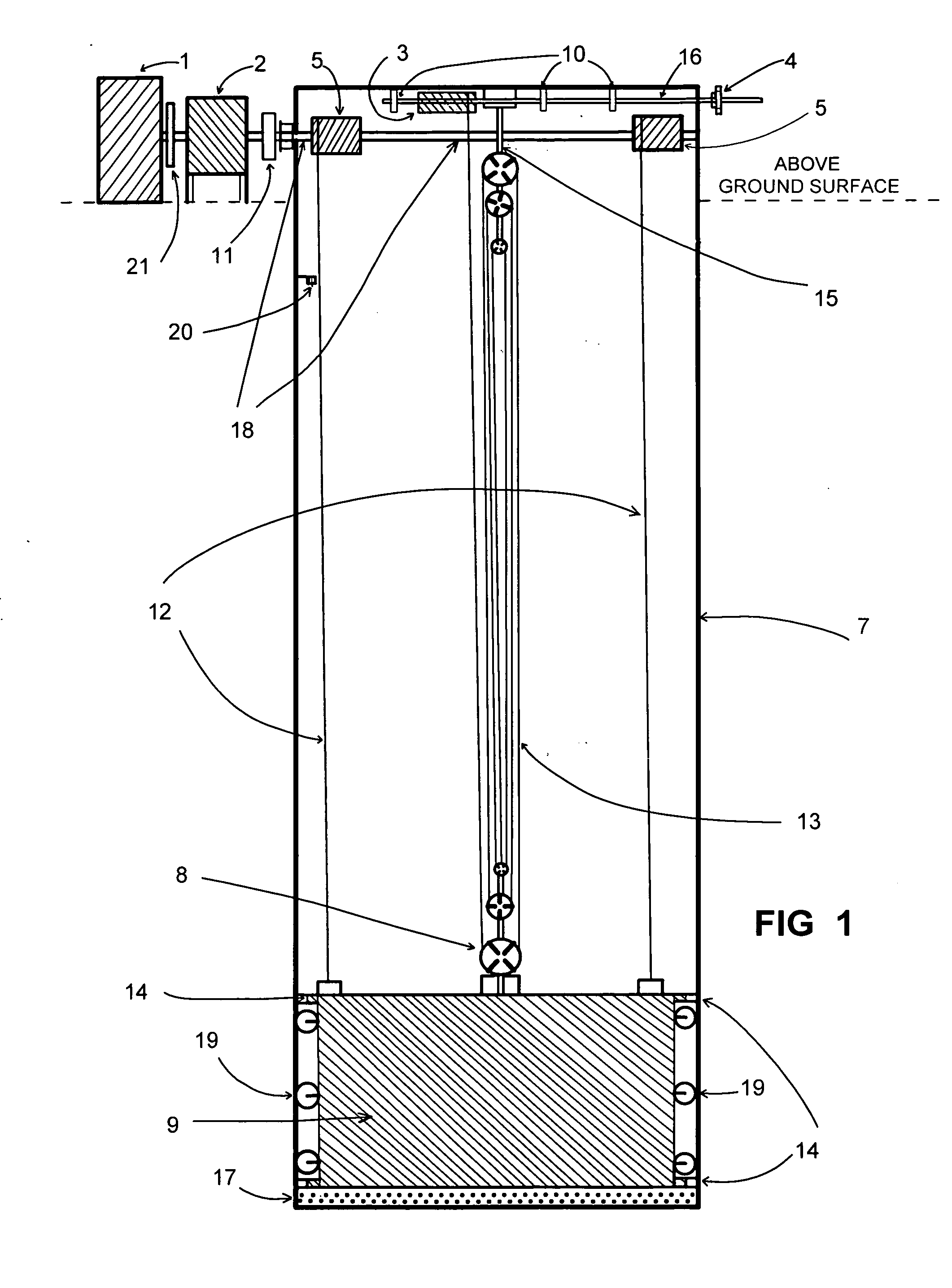
[0010]Referring now to the present invention represents energy storage and generating device designated by the numeral 10 depicted in FIG. 1-2. A simple and basic structure of the energy storage and generator is shown in cross section view in FIG. 1, which can be installed above ground as well below ground. A large cylinder 7 installed in the ground with a heavy piston type stainless steel encased concrete filled slab 9, inserted in the said cylinder. The up and down movement of the piston 9, on the inner cylinder walls of the cylinder 7, is guided with wheels 19, on the piston at tree or four locations which are spaced out evenly on the walls of the cylinder 7, The piston's 9, upper and the lower diameters are fitted with rubber seals 14. The heavy piston's 9 first position is at the bottom of the cylinder, where the piston 9. rest on a rubber pad cushioned by springs 17. The piston 9, is pulled up very slowly with an aid of a pulley system 8, which is used to lift heavy loads. The...


PUM


Abstract

The Gravity energy storage and generating device, main object of the invention is to provide improved mechanical energy storage and release device comprising of the wound and weight energy storing elements. The said device installed in the ground or above where gravity plays a vital role in generating and storing, a large stainless steel encased concrete piston mass that fits in a long cylinder. Both end of the said piston is sealed with two rubber seal ring on the top of the piston and the bottom of piston against the cylinder walls. The cylinders top and the bottom is completely sealed (air tight). The piston's resting point known as first position at the bottom of the cylinder is rubber padded cushion with springs attached to soften the fall of the piston during generating electricity. As the steel cables that is attached at the top of the heavy said piston is pulled up by mean of pulleys. The concrete piston reaches the top also known as second position, you have three forces of energy that is been applied to the piston, gravity, vacuum and air pressure. As the piston descent downwards the shaft attached to the gearbox starts turning, whereby turning the generator.

Description

FIELD OF INVENTION[0001]The invention relates to improved mechanical energy storage and release system of comprising wound energy storage element. More particularly, the invention relates to an improved system for storing and generating energy. This device can be attached to wind mills, or in form of exercise bicycle and any form of energy producing device that has momentum.BACKGROUND OF THE INVENTION[0002]There exit numerous prior related devices which have been attempted to store energy. To date, such systems have failed to be adopted. Weight as energy storage devices have been extensively used in commercial lifts for counter balance. Large construction cranes to counter balance lifting heavy loads.[0003]Accordingly, the present invention improves upon the art in providing an efficient and low maintenance of mechanical energy and release devices that capable of being recharged anywhere, anytime repeatedly, thereby extending the usability. This device primely uses energy storing el...

Claims


Application Information

Patent Timeline
IPC IPC(8): B66D1/36
CPCB66D1/14
Inventor DAYA, ARVIND A.
Owner DAYA ARVIND A
Why Eureka
Try Eureka