Lighting apparatus, especially a reading lamp

a technology of reading lamp and light fixture, which is applied in the direction of vehicle spotlighting, mass transit vehicle lighting, landing aids, etc., can solve the problems of limiting the already restricted space of passengers, reducing the weight of the light fixture, and limiting the available space in the aircraft cabin, so as to achieve a high level of operation convenience

Active Publication Date: 2012-04-12
SCHOTT AG
View PDF10 Cites 18 Cited by
  • Summary
  • Abstract
  • Description
  • Claims
  • Application Information

AI Technical Summary

Benefits of technology

[0010]The object of the present invention, therefore, is to disclose a lighting apparatus that meets the above-mentioned requirements, is reliable, and at the same time counters the disadvantages of the lighting apparatuses known from the prior art. In addition, the lighting apparatus should offer the user a high level of operating convenience and should be visually and tactilely pleasing.
[0011]The object is attained with a lighting apparatus, especially a reading lamp, including a light source, a movable cover to which the light source can be fastened, an adjusting element that cooperates with the cover, and a bearing unit for supporting the cover and the adjusting element; when the adjusting element is actuated, the cover and light source can be rotated around the longitudinal axis of the lighting apparatus and when the cover is actuated, the cover and light source can be moved around a transverse axis extending perpendicular to the longitudinal axis. The adjusting element is easily accessible to the user so that the cover and the light source connected to the cover can be moved around the longitudinal axis by means of the adjusting element and in particular, can be rotated around the longitudinal axis. This makes it possible for the light cone generated by the light source to be adjusted in a manner that is convenient for the user. The design of the lighting apparatus according to the invention makes it possible to reduce the number of required parts, enabling a more compact design of the lighting apparatus. In addition, reducing the number of required parts increases the reliability of the lighting apparatus.
[0012]Preferably, the adjusting element is embodied in the form of an adjusting ring that encompasses the cover in an annular fashion; by actuating the cover, the light source can be pivoted around the transverse axis from a first position into a second position; in the first position, the light source is covered by the adjusting ring or by the bearing unit. Because the light source is covered by the adjusting ring in the first position, it does not produce a light cone that exits from the lighting apparatus. To the user, therefore, it appears to be switched off even when it is switched on. In this design, it is possible to eliminate a switching device for switching the light source on and off, thus permitting a compact design of the lighting apparatus. In this case, the light source can remain switched on all the time. The embodiment of the adjusting element in the form of an adjusting ring that encompasses the cover allows the user to conveniently rotate the cover.

Problems solved by technology

This reading lamp, however, is attached to the monitor so that it can only be used in certain positions.
As a result, the monitor covers part of the information medium, for example, and limits the already restricted space for the passenger.
The available space in aircraft cabins is very limited and in addition, the weight of the lighting apparatus should be reduced as much as possible.
This device has proven useful in actual practice, but places high demands on production precision and requires a relatively complex mechanism.

Method used


Image

  • Lighting apparatus, especially a reading lamp
  • Lighting apparatus, especially a reading lamp
  • Lighting apparatus, especially a reading lamp

Examples


Embodiment Construction

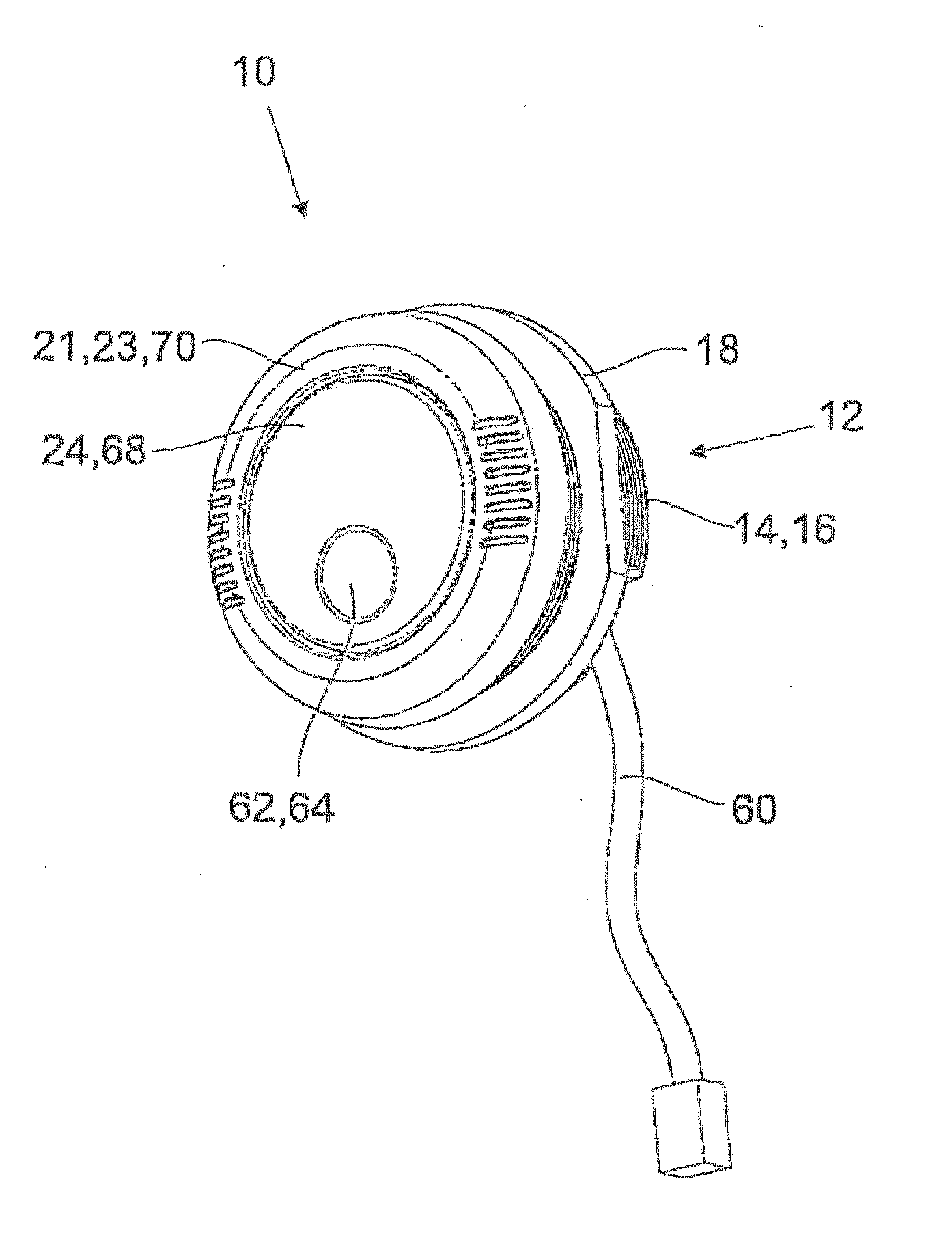
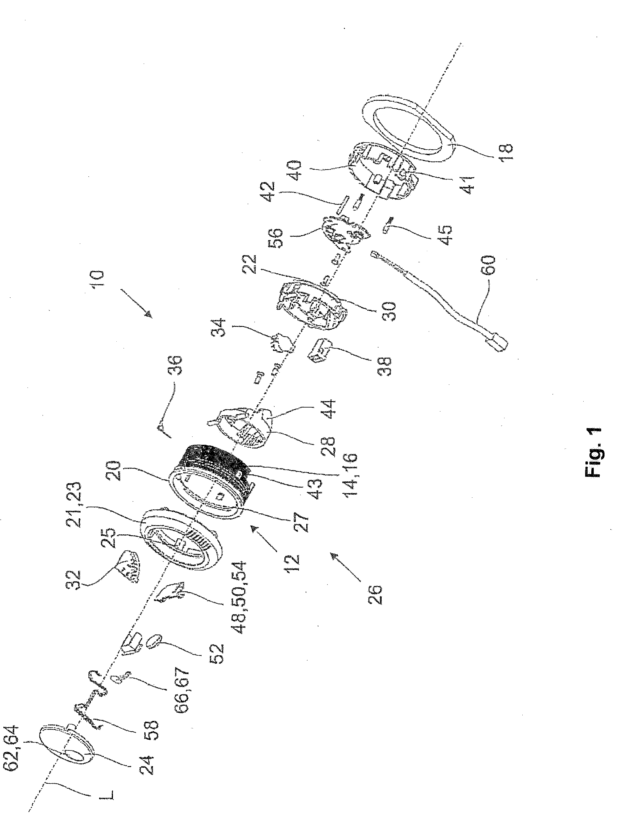
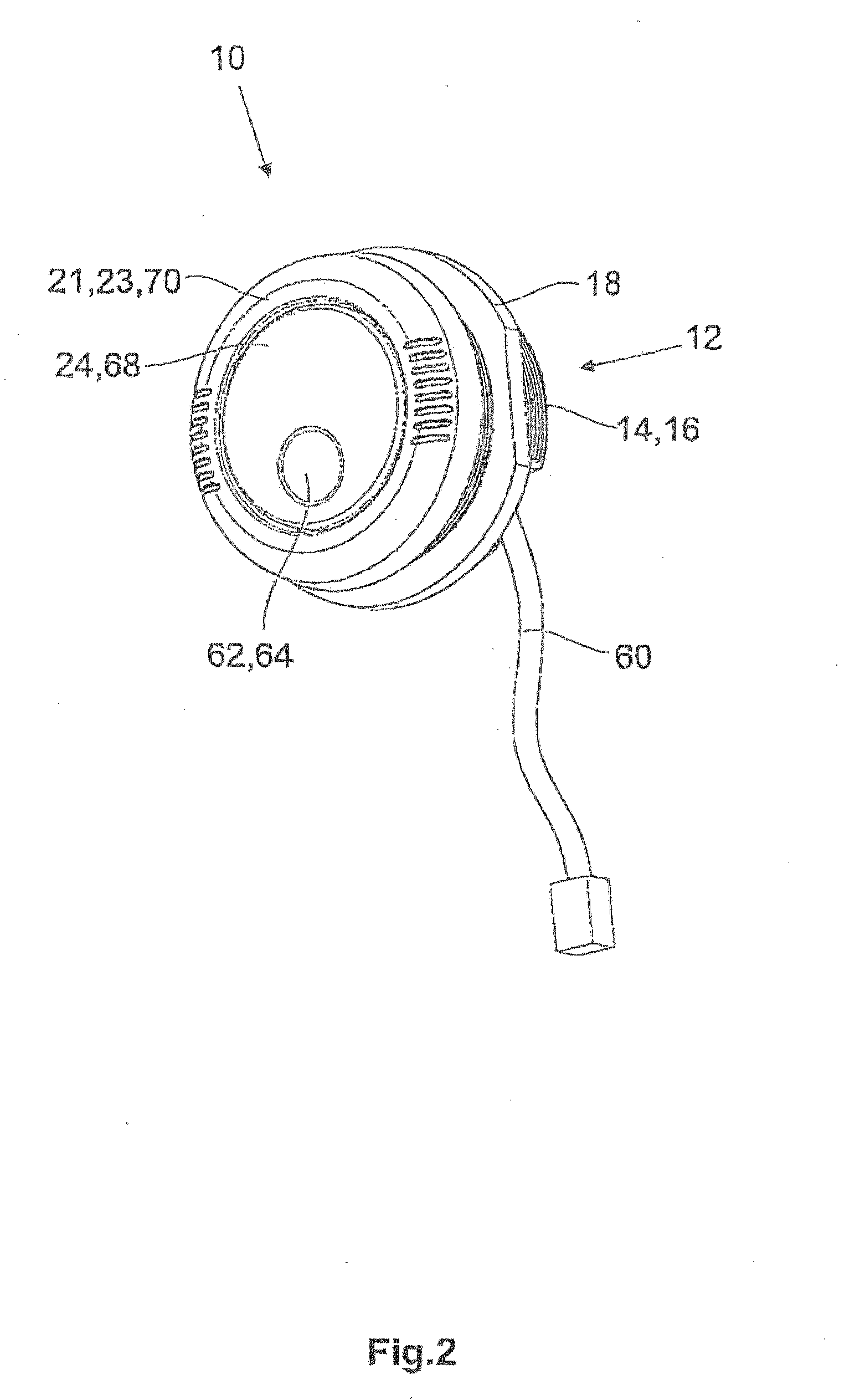
[0037]The exemplary embodiment of the lighting apparatus 10 according to the invention shown in FIG. 1 includes a housing 12 with a circumferential surface 14 on which a thread 16 is provided, onto which a mounting nut 18 can be screwed. The housing 12 has a radially protruding collar 20 to which an adjusting element 21 can be fastened in a way that permits it to be rotated around a longitudinal axis L of the lighting apparatus 10. In the exemplary embodiment shown, the adjusting element 21 is embodied in the form of an adjusting ring 23 that encompasses a cover 24. The adjusting ring 23 is fastened to the housing 12 by means of a bayonet connection. To this end, the adjusting ring 23 has a detent element 25 that cooperates with a projection 27 on the inner surface of the housing 12 and immobilizes the adjusting ring 23 in the axial direction. The projection 27 extends over a wide range along the inner surface so that when fastened in place, the adjusting ring 23 can be rotated over...


PUM


Abstract

The lighting apparatus, especially a reading lamp, has a light source (48), a movable cover (24) to which the light source (48) is fastened, an adjusting element (21) that cooperates with the cover (24), a bearing unit (26) for supporting the cover (24) and an adjusting ring (21). The cover (24) and light source (48) are movable around a longitudinal axis (L) of the lighting apparatus (10) by actuating the adjusting element (21) and the cover (24) and light source (48) are moveable around a transverse axis (Q) extending perpendicular to the longitudinal axis (L) by actuating the cover (24). The lighting apparatus in the form of the reading lamp is particularly useful aboard aircraft, ships, trains, automobiles, or other vehicles.

Description

CROSS-REFERENCE[0001]The invention described and claimed herein below is also described in German Patent Application DE 10 2010 042 287.8, filed on Oct. 11, 2010 in Germany and in U.S. Provisional Application, Ser. 61 / 391,707, filed Oct. 11, 2010. The subject matter of the aforesaid German Patent Application and the U.S. Provisional application is incorporated herein by express reference thereto and provides the basis for a claim of priority of invention for the invention claimed herein below under 35 U.S.C. 119 (a)-(d) and under 35 U.S.C. 119 (e) respectively.BACKGROUND OF THE INVENTION[0002]1. The Field of the Invention[0003]The present invention relates to, a lighting apparatus, especially a reading lamp. Lighting apparatuses of this kind are used as reading lamps, particularly in places where lighting conditions change frequently and the illumination of a particular area should be individually adjustable. Typical places in which they are used include aircraft and trains in which...

Claims


Application Information

Patent Timeline
Patent Type & Authority Applications(United States)
IPC IPC(8): B64D47/02F21V19/02F21V5/04
CPCB60Q3/0253B60Q3/0296B60Q3/0286B64D2011/0053B60Q3/44B60Q3/57B60Q3/76B60Q3/82
Inventor SCHULTHEIS, BERNDWEIL, ACHIMDIETRICH, ANDREASVOGEL, DIRK
Owner SCHOTT AG
Why Eureka
Try Eureka