
Visible and infrared dual mode imaging system

Active Publication Date: 2012-04-12
OMNIVISION TECH INC
View PDF2 Cites 49 Cited by
  • Summary
  • Abstract
  • Description
  • Claims
  • Application Information

AI Technical Summary

Problems solved by technology

The captured infrared images, which interfere with visible light images, often introduce faulty color reproduction to visible light images and may reduce the clarity and quality of visible light images.
The expense and complexity associated with two cameras is a disadvantage.
A disadvantage is that an expensive and failure prone mechanical switch is required to move optical filters.

Method used


Image

  • Visible and infrared dual mode imaging system
  • Visible and infrared dual mode imaging system
  • Visible and infrared dual mode imaging system

Examples


Embodiment Construction

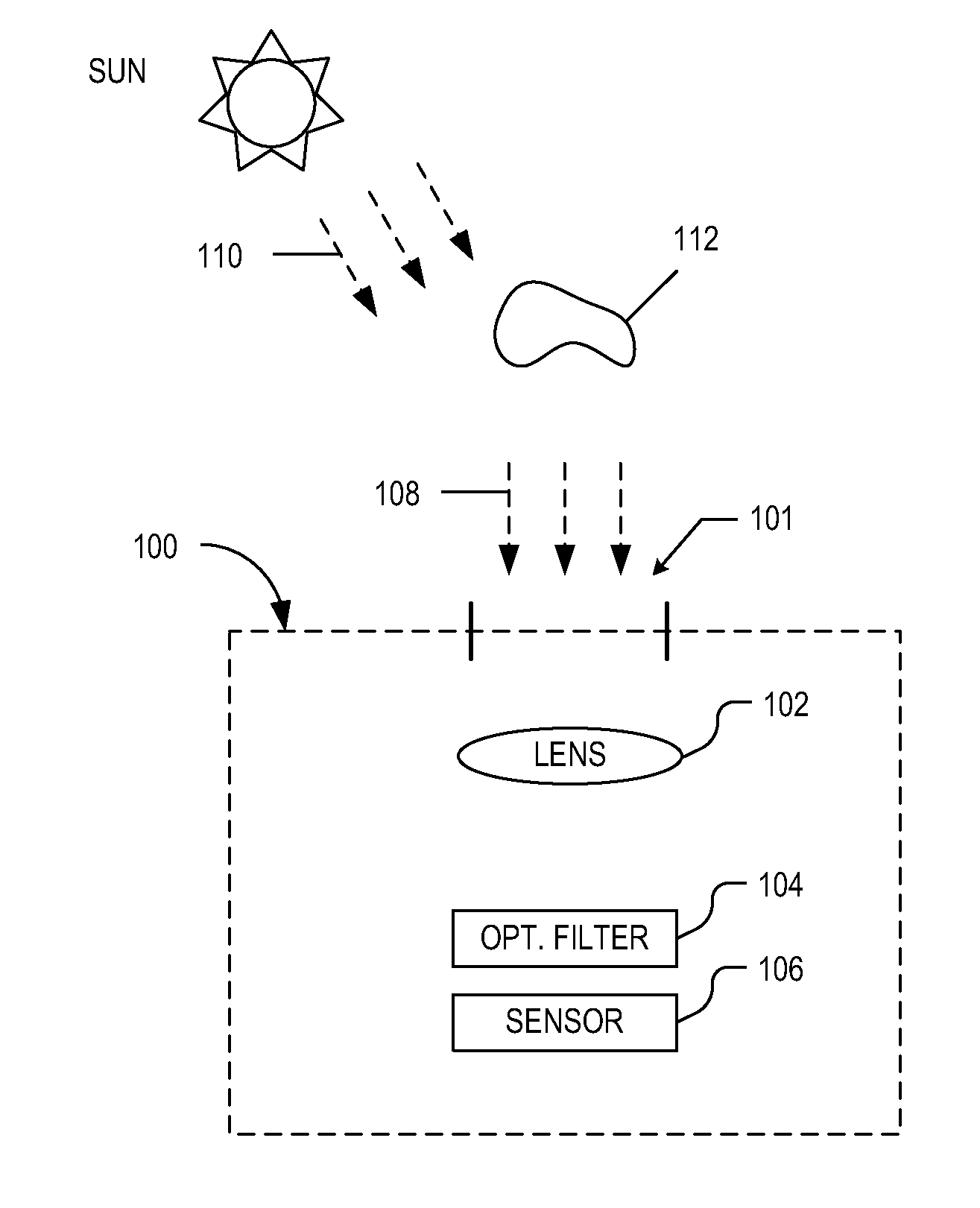
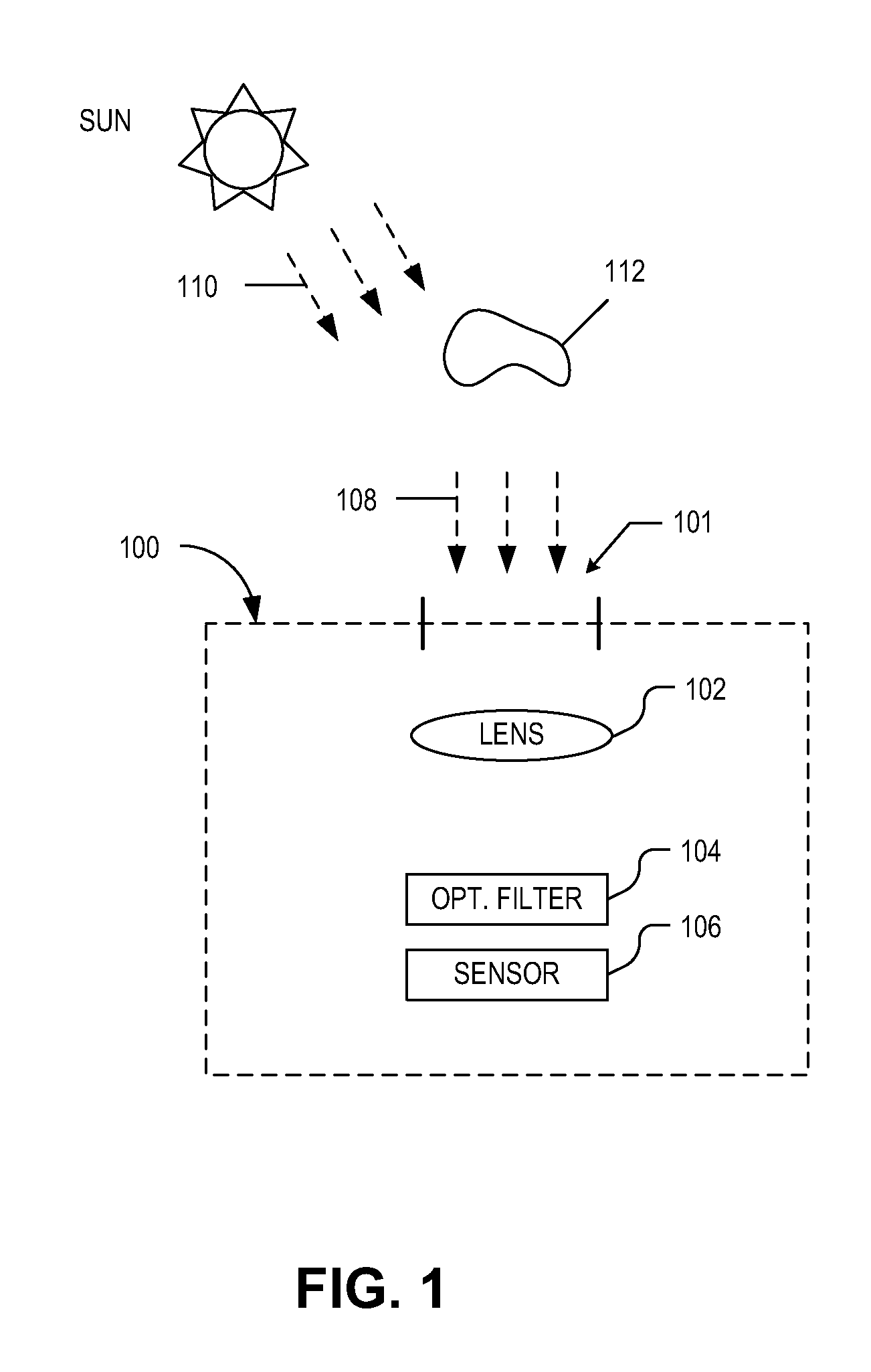
[0016]Embodiments of a system and method of operation for a visible and infrared dual mode imaging system are described herein. In the following description numerous specific details are set forth to provide a thorough understanding of the embodiments. One skilled in the relevant art will recognize, however, that the techniques described herein can be practiced without one or more of the specific details, or with other methods, components, materials, etc. In other instances, well-known structures, materials, or operations are not shown or described in detail to avoid obscuring certain aspects.

[0017]Reference throughout this specification to “one embodiment” or “an embodiment” means that a particular feature, structure, or characteristic described in connection with the embodiment is included in at least one embodiment of the present invention. Thus, the appearances of the phrases “in one embodiment” or “in an embodiment” in various places throughout this specification are not necess...


PUM


Abstract

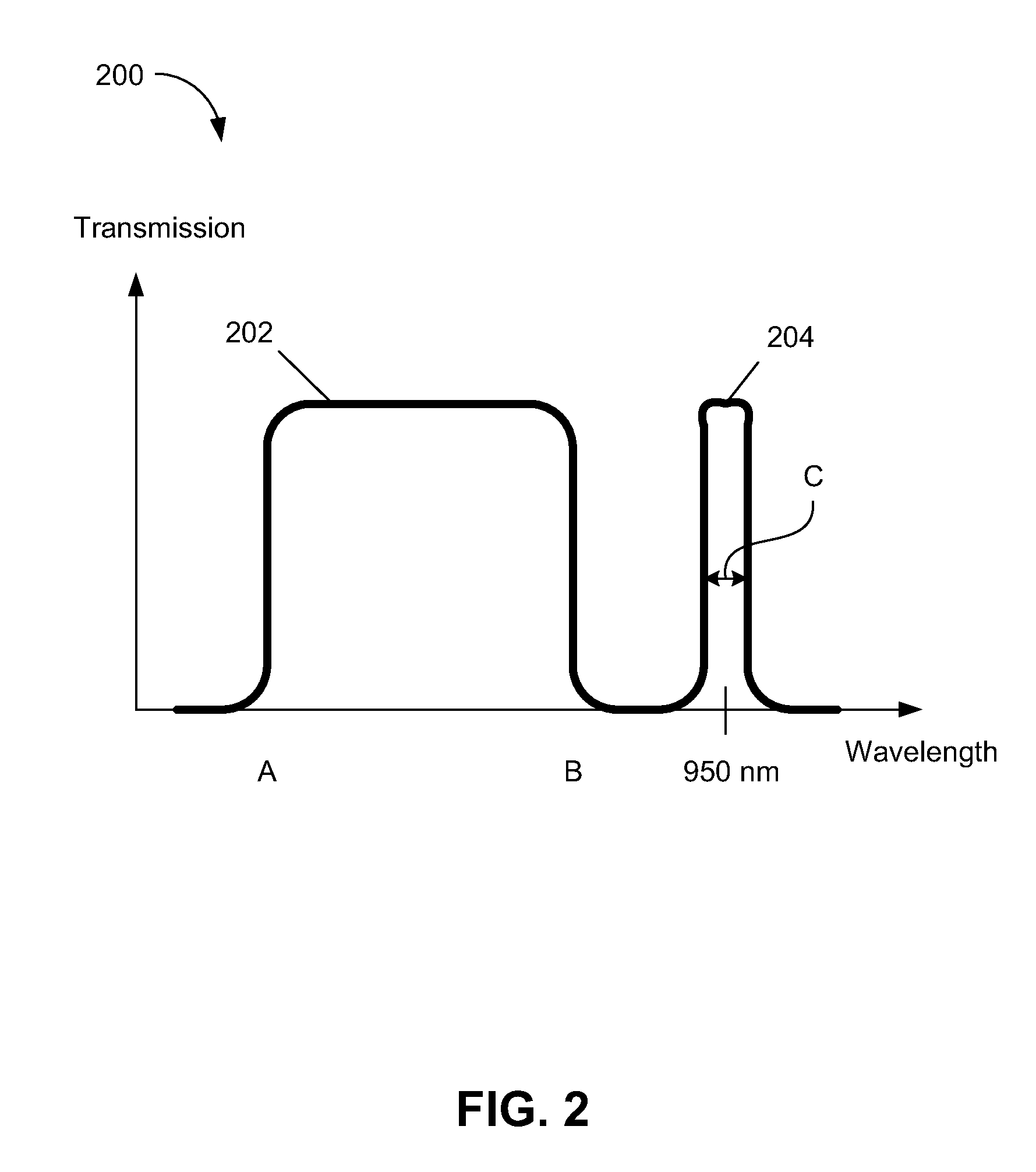
An imaging system includes an image sensor and an optical filter. The image sensor captures image data in response to incident light. The optical filter filters the light and includes a dual window transmission spectrum. The dual window transmission spectrum includes a first transmission window having a first pass band aligned to pass visible light and a second transmission window having a second pass band overlapping with an absorption band of infrared light in Earth's atmosphere.

Description

TECHNICAL FIELD[0001]This disclosure relates generally to imaging systems, and in particular but not exclusively, relates to visible light and infrared light imaging systems.BACKGROUND INFORMATION[0002]Surveillance cameras are commonly used for monitoring an area under surveillance, which may be in a remote location. The still or video images captured by a surveillance camera may be monitored in real-time, recorded for later inspection, or both. A surveillance camera may be placed outdoor and operate 24 hours a day. During daytime, sunlight is the primary illumination source providing visible light. During nighttime, illumination is often provided by a manmade infrared light source. Accordingly, a surveillance system should be sensitive to visible light during the day and infrared light during the night.[0003]However, sunlight contains both infrared radiation as well as visible light. Thus the captured images may contain both visible light images and infrared images, which may not b...

Claims


Application Information

Patent Timeline
IPC IPC(8): G03B17/00H04N5/225
CPCH04N5/33H04N9/04H04N5/332G01J2005/0077G01J2005/204G01J2005/604G01J2003/2806H04N23/11H04N23/10
Inventor WU, FEIMOU, SHUNBOSHAN, JIZHANG
Owner OMNIVISION TECH INC
Learn More