Power line communication method and apparatus for lighting control

a technology of power line communication and lighting control, applied in the direction of electrical equipment, instruments, light sources, etc., can solve the problems of unreliable and expensive conventional power line communication systems

Active Publication Date: 2012-04-19
GE LIGHTING SOLUTIONS LLC
View PDF1 Cites 74 Cited by
  • Summary
  • Abstract
  • Description
  • Claims
  • Application Information

AI Technical Summary

Benefits of technology

[0002]Transmitter and receiver apparatus and techniques are provided for transmitting control information to a ballast or driver in which the transmitter selectively interrupts power delivery in select AC line power cycles to indicate data of a first binary state and uninterrupted power cycles indicate a second binary state with the receiver decoding the message data bits of different binary states based at least partially on the interruptions.

Problems solved by technology

However, this communication technique requires filter trapping to confine the signal to the targeted ballasts, and the ballast must have a receiver to interpret signals that are superimposed on the power line.
Accordingly, conventional power line communications systems are expensive and unreliable.

Method used


Image

  • Power line communication method and apparatus for lighting control
  • Power line communication method and apparatus for lighting control
  • Power line communication method and apparatus for lighting control

Examples


Embodiment Construction

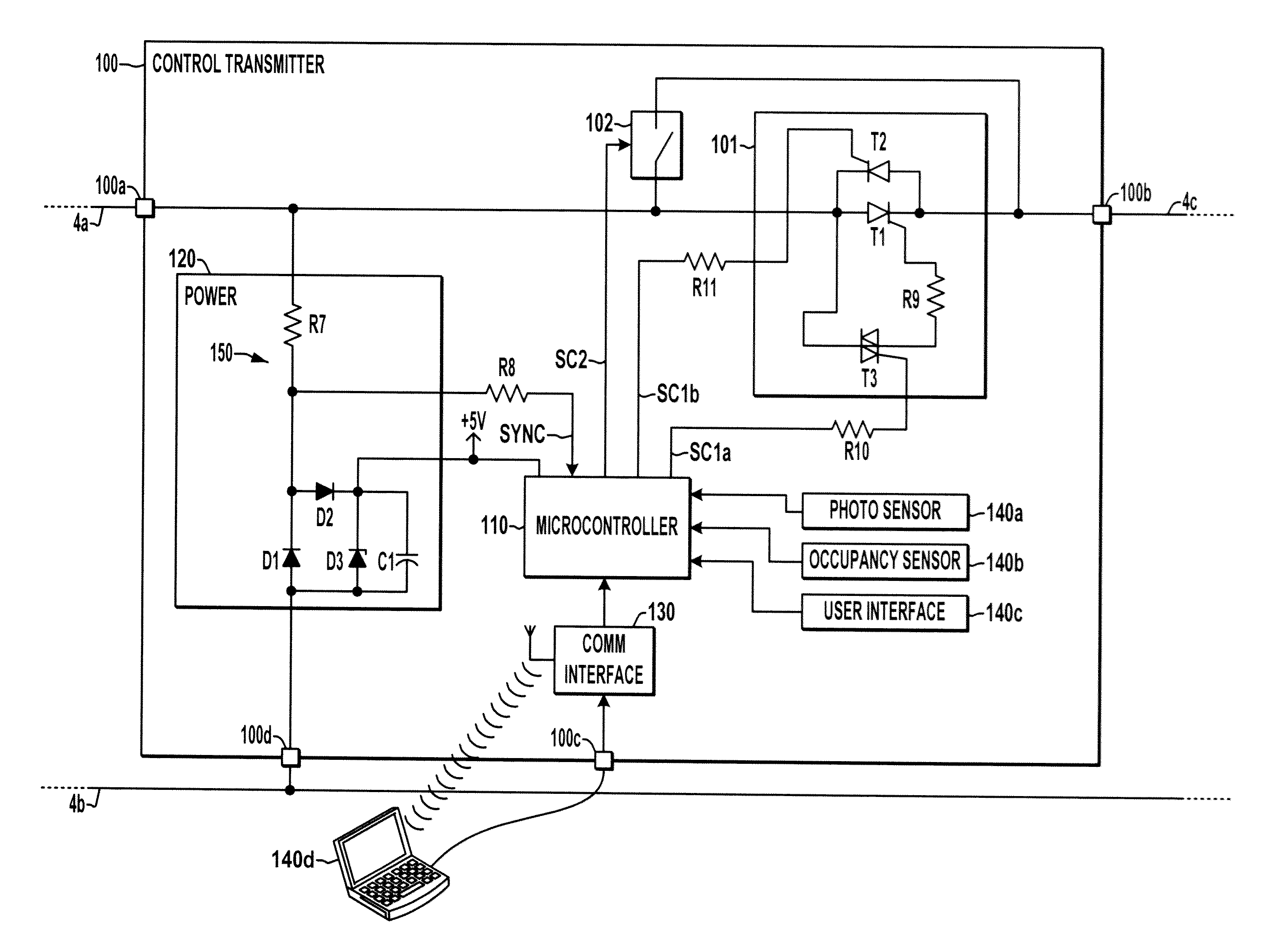
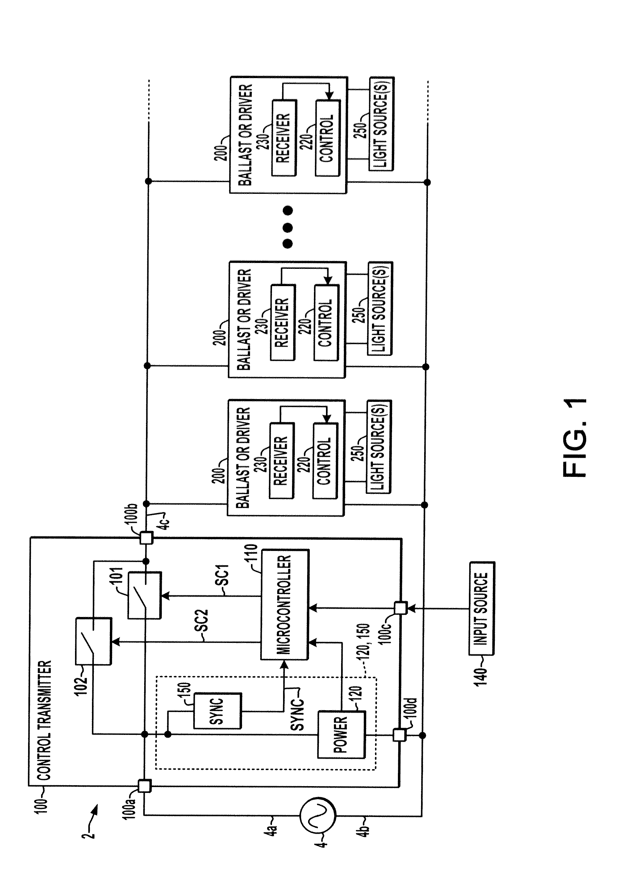
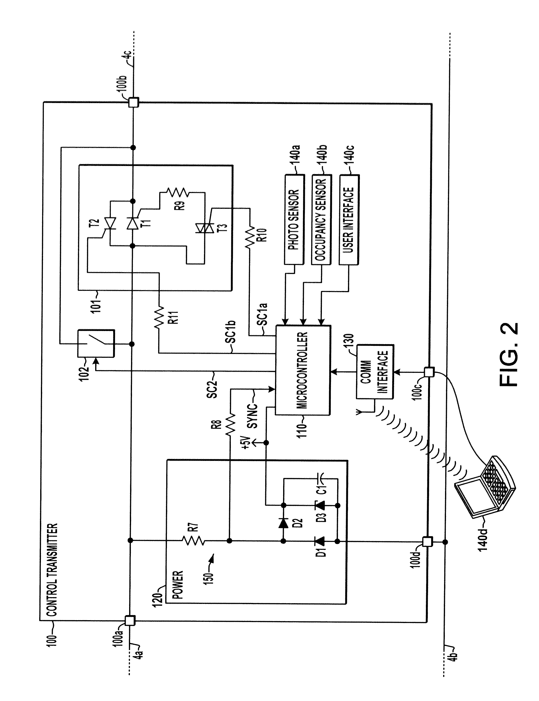
[0021]Referring now to the drawings, where like reference numerals are used to refer to like elements throughout, and wherein the various features are not necessarily drawn to scale, the present disclosure relates to communications techniques and apparatus for communicating with lighting system drivers or ballasts using power lines by selective interruption of provided power. FIG. 1 illustrates a lighting system 2 equipped with a control transmitter apparatus 100 connected between an AC power source 4 and several ballasts or drivers 200 having receivers 220 in which one or more aspects of the disclosure may be carried out. FIG. 2 illustrates further details of an exemplary control transmitter 100 and FIG. 3 shows further details of an exemplary ballast / driver receiver apparatus in the system of FIG. 1. The control transmitter apparatus 100 communicates with the ballasts or drivers 200 through lighting system power connection 4c (e.g., power line) in which load-side power connections...


PUM


Abstract

A transmitter apparatus and a ballast/driver receiver apparatus are presented for transmitting control information through a lighting system power line connection to a ballast or driver in which the transmitter selectively interrupts power delivery in select AC line power cycles to indicate data of a first binary state an uninterrupted power cycles indicate a second binary state with the receiver decoding the message data bits of different binary states based at least partially on the interruptions.

Description

BACKGROUND OF THE DISCLOSURE[0001]Remote control of electronic ballasts and / or LED drivers via the power line connections allows improved functionality without additional control wiring. Conventional power line carrier (PLC) circuits transmit a modulated high frequency carrier signal through the power wiring to which a lighting system ballast is connected. However, this communication technique requires filter trapping to confine the signal to the targeted ballasts, and the ballast must have a receiver to interpret signals that are superimposed on the power line. Moreover the carrier signal may be significantly attenuated by inherent filtering properties of the power lines over which they are transmitted. Accordingly, conventional power line communications systems are expensive and unreliable. Thus, there remains a need for improved communications systems to provide control information to lighting ballasts using existing power lines.SUMMARY OF THE DISCLOSURE[0002]Transmitter and rece...

Claims


Application Information

Patent Timeline
Patent Type & Authority Applications(United States)
IPC IPC(8): H05B41/36
CPCH05B37/0263H05B47/185
Inventor ILYES, LASZLO SANDORTRACY, DAVID JOSEPH
Owner GE LIGHTING SOLUTIONS LLC
Why Eureka
Try Eureka