Multi-view autostereoscopic display device

a display device and multi-view technology, applied in the field of autostereoscopic display devices, can solve the problems of inability to meet the needs of users at a fixed position, inability to achieve light efficiency, and inability to sacrifice resolution for certain applications, so as to improve image uniformity, reduce banding, and increase the resolution at the output.

Inactive Publication Date: 2012-04-19
KONINKLIJKE PHILIPS ELECTRONICS NV
View PDF4 Cites 18 Cited by
  • Summary
  • Abstract
  • Description
  • Claims
  • Application Information

AI Technical Summary

Benefits of technology

[0027]In another example, the first and second polarization-sensitive lenticular arrays have the same lens pitch, and wherein the effective lens position of one lenticular array is shifted laterally with respect to the other by an amount which is a non-integer multiple of the pitch between the pixel elements. This provides additional views at inter-pixel locations, thereby increasing the resolution at the output. By generating additional views, the image uniformity is improved and there is a reduction in banding. The amount of shift can comprise half the pitch between the individual pixel elements. However, the shift can instead comprise half the pitch between the lens elements. If each lens element width covers an odd number of pixels, this again gives shift including a half pixel, thereby enabling intermediate images to be formed, which increase the resolution.
[0028]The first and second polarization-sensitive lenticular arrays can each comprise elongate lenticular lenses, having an elongate axis offset from the column direction of the display panel. This is a known way to spread the loss of resolution between the row and column directions.
[0029]In one arrangement, the elongate axis offset for one lenticular array is different to the elongate axis offset of the other lenticular array. This enables different viewing effects to be obtained by the two lenticular arrays, for example depending on the image content.
[0030]The elongate axis of one lenticular array can be offset by less than 40 degrees from the column direction and the elongate axis of the other lenticular array can be offset by less than 40 degrees from the row direction. This enables the display to be rotatable between portrait and landscape modes, with one of the 3D modes for each. In each mode, the lenticular is closer to the vertical than the horizontal. For example the landscape mode may be associated with an angle less than 20 degrees to the vertical when the display is oriented for that mode (e.g. tan α=⅓), and the portrait mode can be associated with a larger slant angle to the vertical when the display is oriented for that mode (e.g. tan α=⅔). In this arrangement, the slant in the portrait mode is larger, so that the loss in resolution is transferred more to the columns (of which there are more in the portrait orientation). Other combinations of slant angle are possible—essentially, one slant angle is optimized for the portrait mode and the other is optimized for the landscape mode.

Problems solved by technology

A drawback of this type of two-view display design is that the viewer has to be at a fixed position, and can only move approximately 3 cm to the left or right.
The barrier arrangement is simple to produce but is not light efficient.
This sacrifice in resolution is unacceptable for certain applications, such as the display of small text characters for viewing from short distances.
The two-dimensional display mode cannot, of course, provide a stereoscopic image.
The resulting display is capable of providing stereoscopic images, but has the inevitable resolution loss mentioned above.
For the 3D mode of operation, a major dilemma is caused by the fact that on the one hand a large number of views per angle is needed for a good 3D impression and on the other hand a small number of views is needed for a sufficiently high resolution (i.e. number of pixels) per view.
A major drawback of using a high number of views is that the image resolution per view is greatly reduced.
Increasing the number of views thus improves the 3D impression but reduces the image resolution as perceived by the viewer.
These arrangements result in a complicated imaging arrangement (i.e. the barrier arrangement or the lens arrangement), and difficulties can arise in achieving the desired switching speed for the imaging arrangement.

Method used


Image

  • Multi-view autostereoscopic display device
  • Multi-view autostereoscopic display device
  • Multi-view autostereoscopic display device

Examples


Embodiment Construction

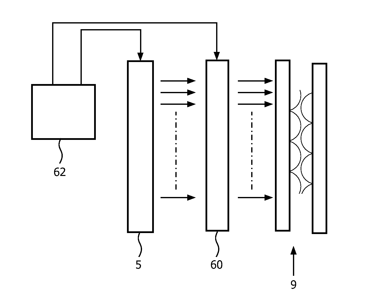
[0045]The invention provides a switchable autostereoscopic display device in which an imaging arrangement directs the output from different pixels to different spatial positions to enable a stereoscopic image to be viewed. The display is controllable between two 3D modes based on the polarization of the light provided to the imaging arrangement, in order to enable the resolution or number of images to be increased using a time multiplex approach, or to enable additional output functions to be provided.

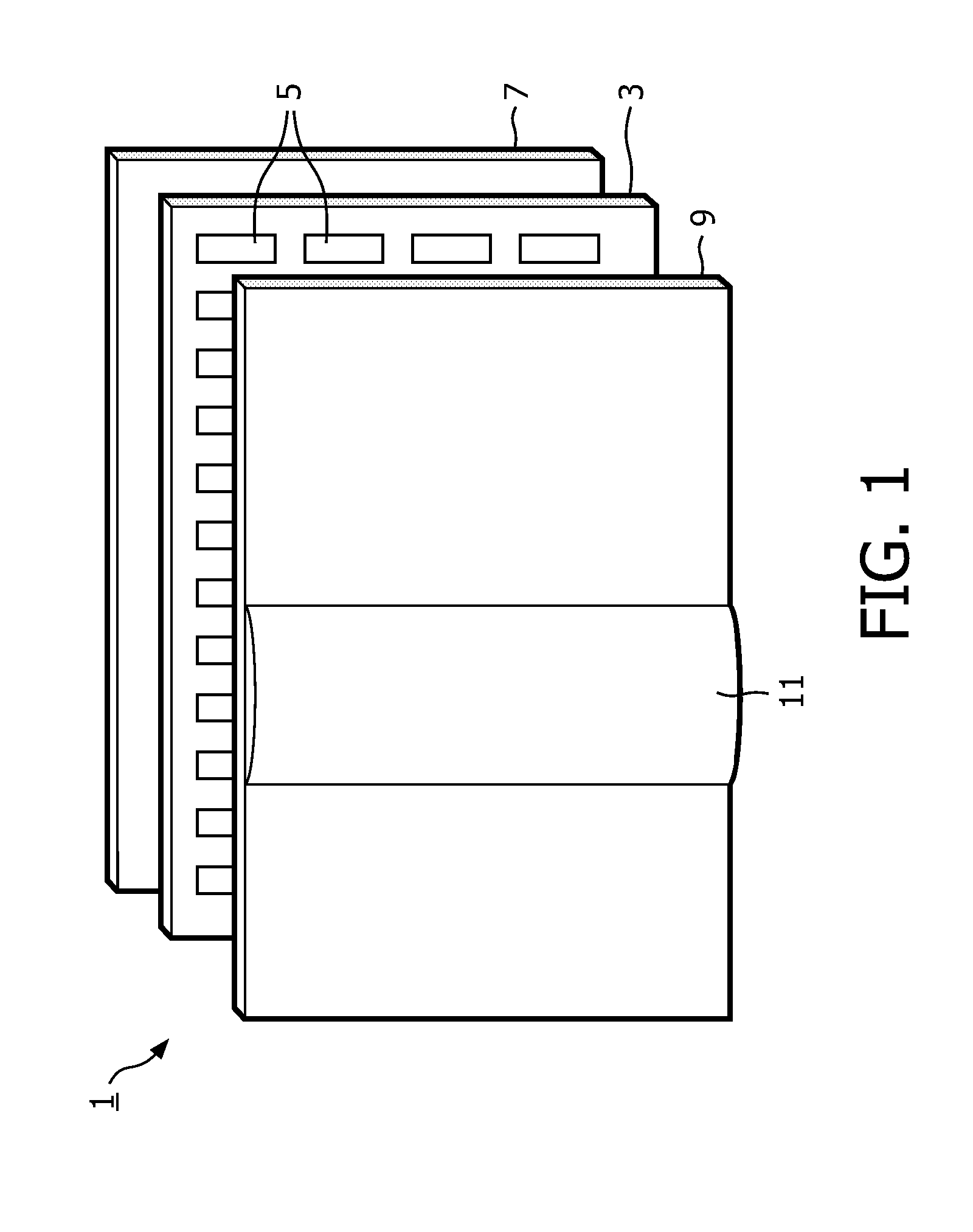
[0046]FIG. 1 is a schematic perspective view of a known direct view autostereoscopic display device 1. The known device 1 comprises a liquid crystal display panel 3 of the active matrix type that acts as a spatial light modulator to produce the display.

[0047]The display panel 3 has an orthogonal array of display pixels 5 arranged in rows and columns. For the sake of clarity, only a small number of display pixels 5 are shown in the Figure. In practice, the display panel 3 might comprise...


PUM


Abstract

An autostereoscopic display device comprises a display panel (3) having an array of display pixel elements (5) for producing a display, the display pixel elements being arranged in rows and columns. An imaging arrangement (9) directs the output from different pixel elements to different spatial positions to enable a stereoscopic image to be viewed. The imaging arrangement comprises first and second polarization-sensitive lenticular arrays (50,52), wherein the light incident on the imaging arrangement is controllable to have one of two possible polarizations, and wherein each of the two possible polarizations gives a different 3D mode. These multiple modes can be used to increase the resolution, or increasing the number of views, or provide additional functionality to the display device.

Description

FIELD OF THE INVENTION[0001]This invention relates to an autostereoscopic display device of the type that comprises a display panel having an array of display pixels for producing a display and an imaging arrangement for directing different views to different spatial positions.BACKGROUND OF THE INVENTION[0002]A first example of an imaging arrangement for use in this type of display is a barrier, for example with slits that are sized and positioned in relation to the underlying pixels of the display. The viewer is able to perceive a 3D image if his / her head is at a fixed position. The barrier is positioned in front of the display panel and is designed so that light from the odd and even pixel columns is directed towards the left and right eye of the viewer.[0003]A drawback of this type of two-view display design is that the viewer has to be at a fixed position, and can only move approximately 3 cm to the left or right. In a more preferred embodiment there are not two sub-pixel column...

Claims


Application Information

Patent Timeline
Patent Type & Authority Applications(United States)
IPC IPC(8): G06T15/00G02B30/29
CPCG02B27/2214G02B27/26H04N13/0454H04N13/045H04N13/0404H04N13/305H04N13/354H04N13/359G02B30/25G02B30/29G02B30/27
Inventor PIJLMAN, FETZEDE ZWART, SIEBE TJERKKRIJN, MARCELLINUS PETRUS CAROLUS MICHAEL
Owner KONINKLIJKE PHILIPS ELECTRONICS NV
Why Eureka
Try Eureka