
Ladder attachment

Inactive Publication Date: 2012-04-26
CAM K
View PDF2 Cites 19 Cited by
  • Summary
  • Abstract
  • Description
  • Claims
  • Application Information

AI Technical Summary

Benefits of technology

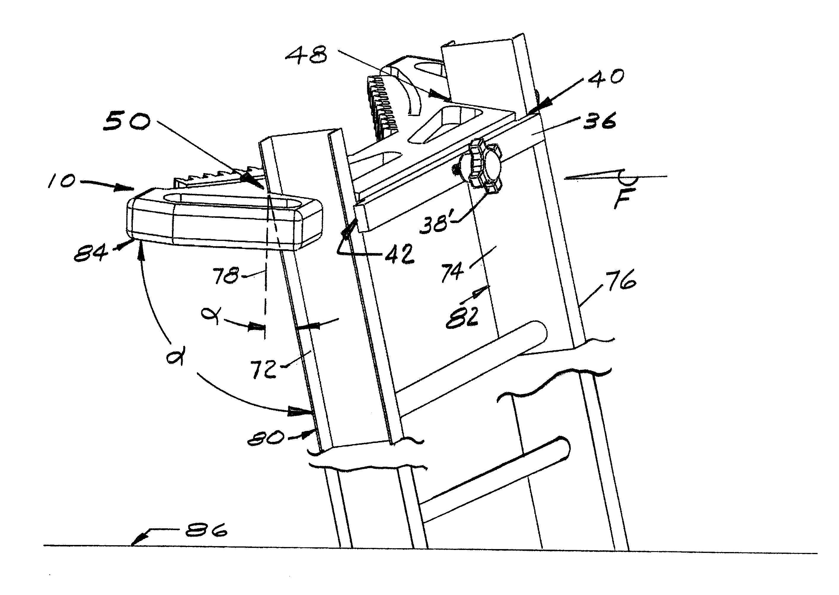
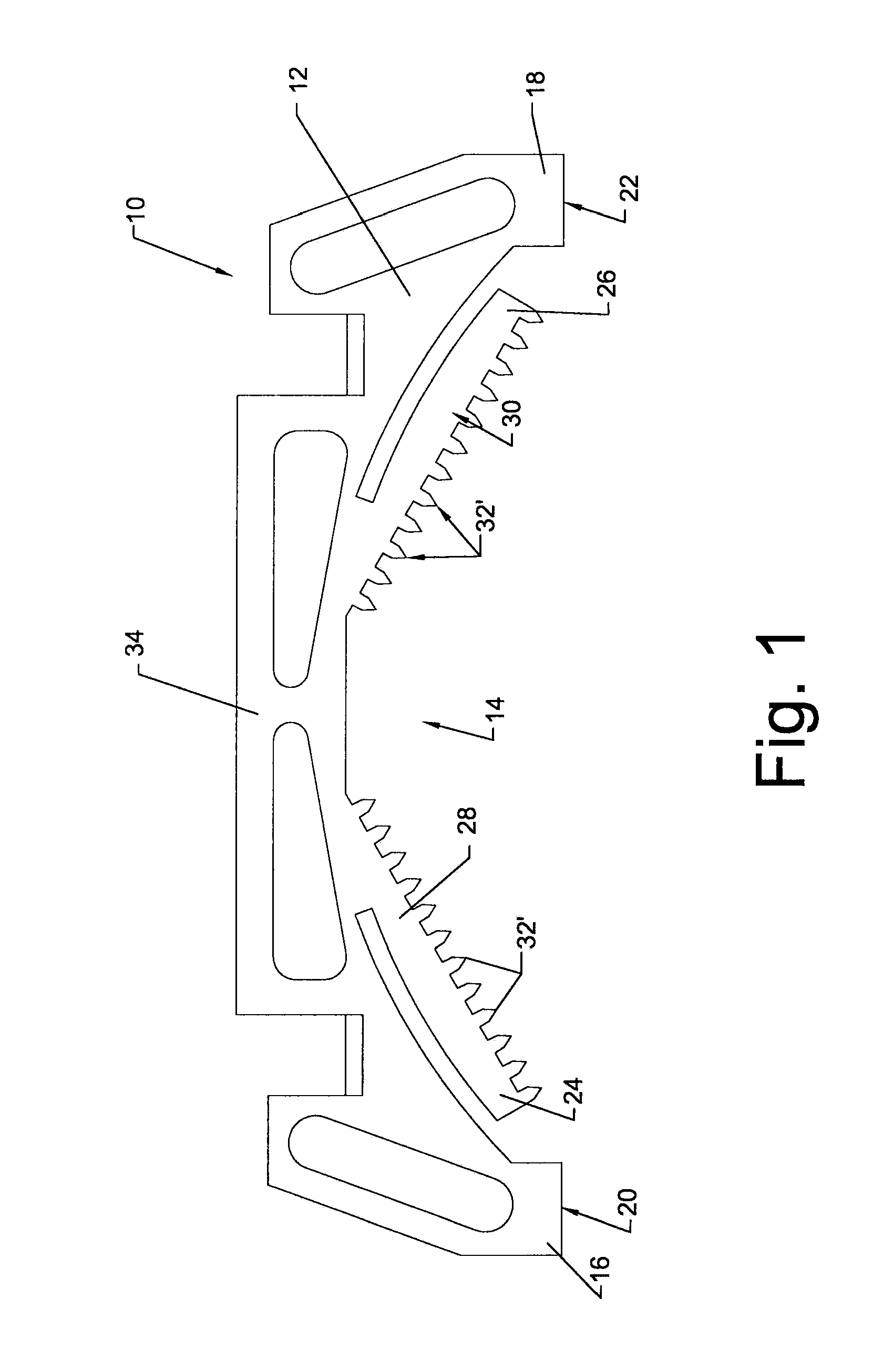
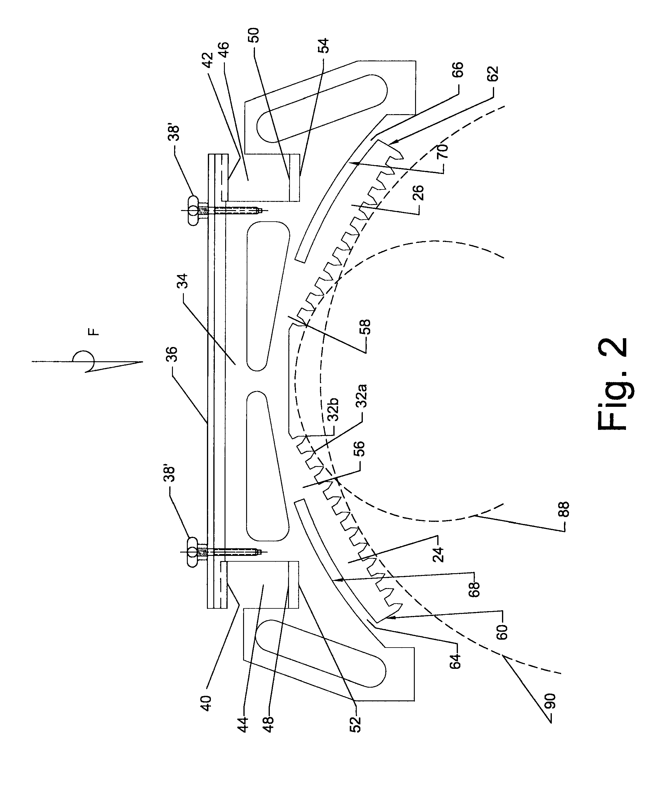
[0006]According to further embodiments, a ladder attachment includes an elastomeric member having a rigid body including a concave recess created between first and second end legs. First and second gripper wings are individually connected at first and second connecting ends to a body cross member of the body and extend into the concave recess, each having multiple teeth oriented away from the body. The first and second gripper wings are individually separated from the body by first and second slots such that the first and second gripper wings elastically deflect into the first and second slots and toward the body by a force acting on the body. The first and second gripper wings each have a maximum thickness at the first and second connecting ends at the body cross member, and first and second free ends which are thinner than the first and second connecting ends to provide elastic flexibility of the first and second gripper wings.

Problems solved by technology

Known attachments for stabilizing lean type ladders when supported against flat surfaces or against the trunks of trees or utility poles do not provide for automatic engagement between the attachment and the tree trunk or utility pole.

Method used


Image

  • Ladder attachment
  • Ladder attachment
  • Ladder attachment

Examples


Embodiment Construction

[0017]Example embodiments will now be described more fully with reference to the accompanying drawings.

[0018]Example embodiments are provided so that this disclosure will be thorough, and will fully convey the scope to those who are skilled in the art. Numerous specific details are set forth such as examples of specific components, devices, and methods, to provide a thorough understanding of embodiments of the present disclosure. It will be apparent to those skilled in the art that specific details need not be employed, that example embodiments may be embodied in many different forms and that neither should be construed to limit the scope of the disclosure. In some example embodiments, well-known processes, well-known device structures, and well-known technologies are not described in detail.

[0019]The terminology used herein is for the purpose of describing particular example embodiments only and is not intended to be limiting. As used herein, the singular forms “a,”“an,” and “the” ...


PUM


Abstract

A ladder attachment includes an elastomeric member having a rigid body including a concave recess created between first and second end legs. First and second gripper wings are connected to the elastomeric member and extend into the concave recess. Each gripper wing has multiple teeth oriented away from the body. The first and second gripper wings are separated from the body by first and second slots. The first and second gripper wings elastically deflect into the first and second slots and toward the body by a force acting on the body. The body has first and second apertures including first and second body angled surfaces oriented at an acute angle with respect to a line extending through the body and perpendicular to a planar body surface. The first and second gripper wings have a maximum thickness at the first and second connecting ends, and thinner first and second free ends.

Description

FIELD[0001]The present disclosure relates to attachment devices to stabilize rung and leaning ladders.BACKGROUND[0002]This section provides background information related to the present disclosure which is not necessarily prior art.[0003]Attachments for stabilizing ladders designed to lean against an object to prevent the ladder from tipping or sliding when propped up against a supporting structure are known. An example is the ladder attachment disclosed in U.S. Pat. No. 7,575,097 which is co-owned by the assignee of the present application. Known attachments for stabilizing lean type ladders when supported against flat surfaces or against the trunks of trees or utility poles do not provide for automatic engagement between the attachment and the tree trunk or utility pole.SUMMARY[0004]This section provides a general summary of the disclosure, and is not a comprehensive disclosure of its full scope or all of its features.[0005]According to several embodiments, a ladder attachment inc...

Claims


Application Information

Patent Timeline
IPC IPC(8): E06C7/48E06C7/00
CPCE06C1/06E06C7/482E06C7/48
Inventor SCHIENKE, CHRISTOPHER J.ASSELIN, DENNIS A.
Owner CAM K
Learn More