
Intravascular stent having high fatigue performance

a stent and high fatigue performance technology, applied in the field of expandable endoprosthesis devices, can solve problems such as fatigue failure, achieve the effects of maintaining compliance, facilitating stent expansion, and facilitating stent expansion

Active Publication Date: 2019-11-05
ABBOTT CARDIOVASCULAR
View PDF5 Cites 0 Cited by
  • Summary
  • Abstract
  • Description
  • Claims
  • Application Information

AI Technical Summary

Benefits of technology

The present invention is a stent that is designed to be flexible along its length, making it easier to insert into narrow body lumens. However, the stent has structural features that improve its ability to withstand fatigue and pressure. The stent consists of multiple rings that are interconnected by links, which provide stability and flexibility. The rings have a serpentine shape with at least one U-shaped element. The combination of these rings and links creates a stent pattern that allows the stent to be highly flexible along its length.

Problems solved by technology

Along with crimping and expansion forces, implanting the stent in the dynamic environment in a curved artery section causes stresses in the stent structure that can result in fatigue failure.

Method used


Image

  • Intravascular stent having high fatigue performance
  • Intravascular stent having high fatigue performance
  • Intravascular stent having high fatigue performance

Examples


Embodiment Construction

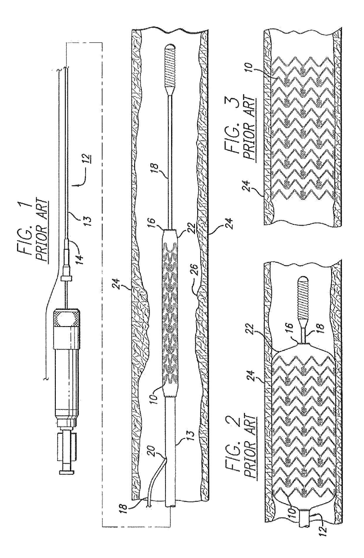
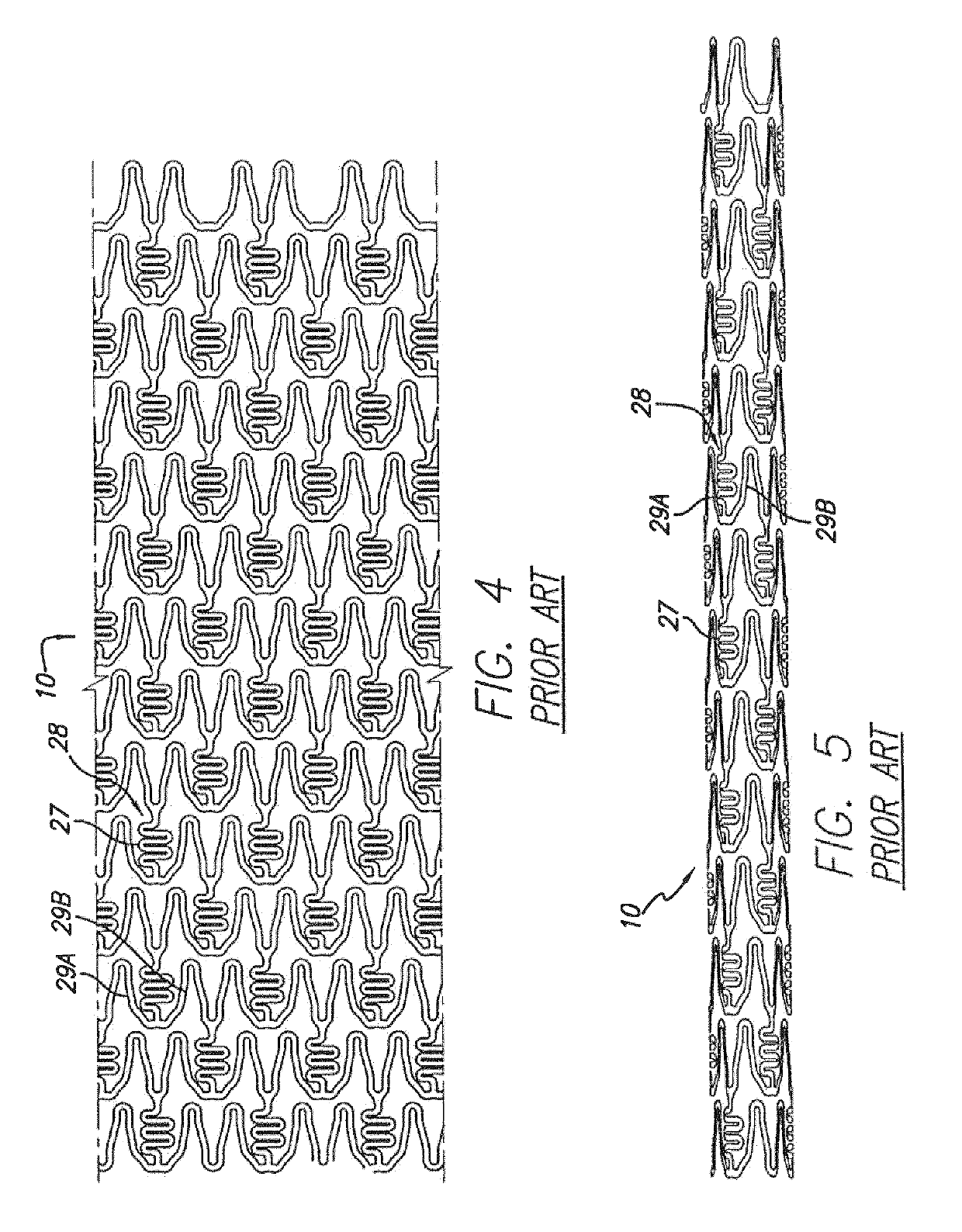
[0031]Turning to the drawings, FIG. 1 depicts a prior art stent 10 mounted on a conventional catheter assembly 12 which is used to deliver the stent and implant it in a body lumen, such as a coronary artery, peripheral artery, or other vessel or lumen within the body. The catheter assembly includes a catheter shaft 13 which has a proximal end 14 and a distal end 16. The catheter assembly is configured to advance through the patient's vascular system by advancing over a guide wire 18 by any of the well-known methods of an over the wire system (not shown) or a well-known rapid exchange catheter system, such as the one shown in FIG. 1.

[0032]Catheter assembly 12 as depicted in FIG. 1 is of the well-known rapid exchange type which includes an RX port 20 where the guide wire 18 exits the catheter. The distal end of the guide wire 18 exits the catheter distal end 16 so that the catheter advances along the guide wire on a section of the catheter between the RX port 20 and the catheter dista...


PUM


Abstract

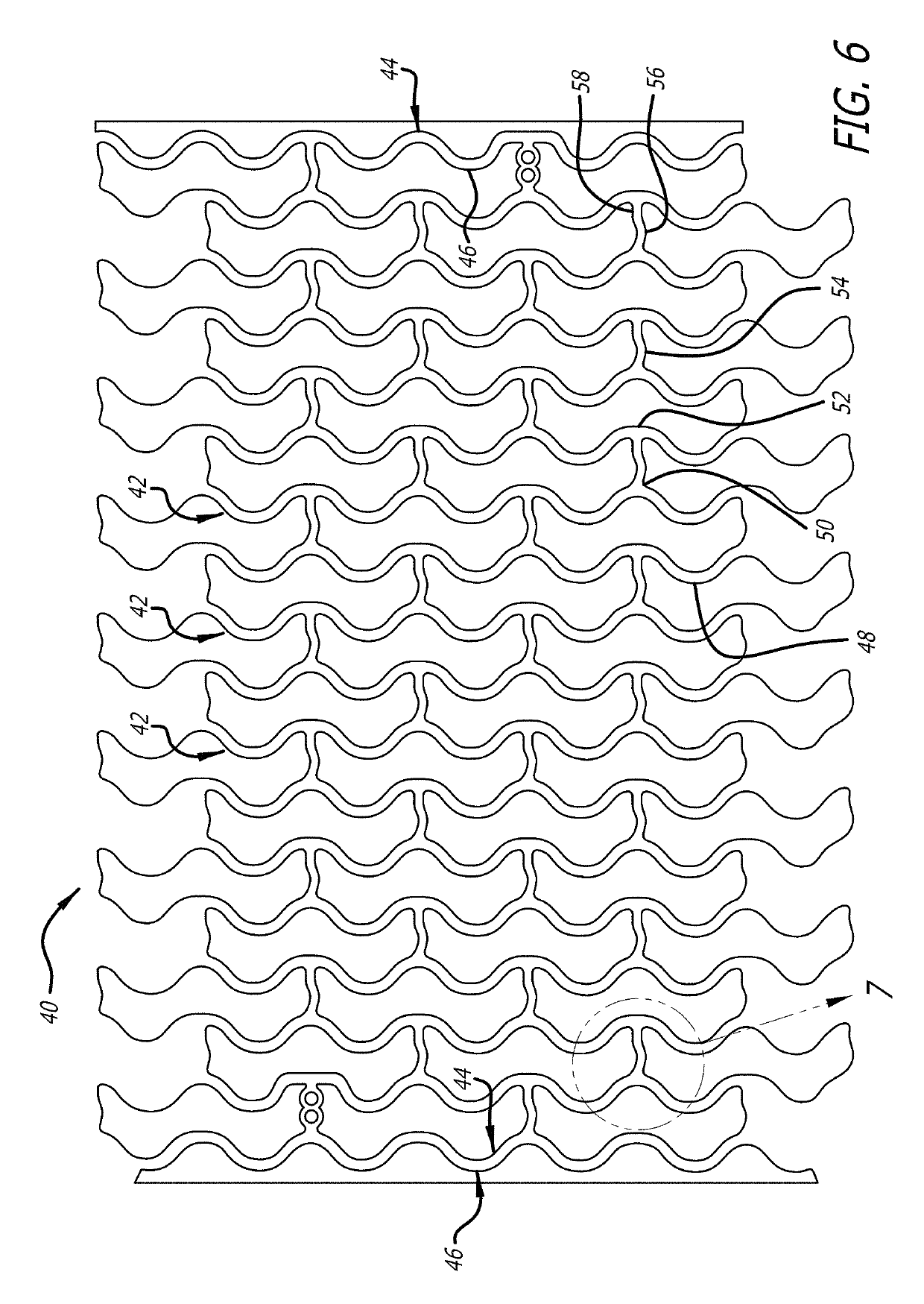
This invention is directed to an expandable stent for implantation in a body lumen, such as an artery, and a method for making it from a single length of tubing. The stent consists of a plurality of radially expandable cylindrical elements generally aligned on a common axis and interconnected by one or more links. A Y-shaped member is comprised of a U-shaped member and a link having a curved portion and a straight portion to improve the flexibility and thereby improve the fatigue performance of the Y-link junction.

Description

BACKGROUND[0001]This invention relates to expandable endoprosthesis devices, generally called stents, which are adapted to be implanted into a patient's body lumen, such as blood vessel, to maintain the patency thereof. These devices are very useful in the treatment of atherosclerotic stenosis in blood vessels.[0002]Various means have been described to deliver and implant stents. One method frequently described for delivering a stent to a desired intraluminal location includes mounting the expandable stent on an expandable member, such as a balloon, provided on the distal end of an intravascular catheter, advancing the catheter to the desired location within the patient's body lumen, inflating the balloon on the catheter to expand the stent into a permanent expanded condition and then deflating the balloon and removing the catheter.[0003]The stent must be able to satisfy a number of mechanical requirements. First, the stent must be capable of withstanding the structural loads, namel...

Claims


Application Information

Patent Timeline
Patent Type & Authority Patents(United States)
IPC IPC(8): A61F2/06A61F2/89A61F2/915
CPCA61F2/915A61F2/89A61F2002/91566A61F2002/91533A61F2002/91558
Inventor TA, DIEM UYENESWARAN, SENTHIL K.BEI, NIANJIONG JOAN
Owner ABBOTT CARDIOVASCULAR
Learn More