Nail-pushing rod restoring apparatus for pneumatic nail gun

Inactive Publication Date: 2012-04-26
DE POAN PNEUMATIC
View PDF14 Cites 26 Cited by
  • Summary
  • Abstract
  • Description
  • Claims
  • Application Information

AI Technical Summary

Benefits of technology

[0015]Each of the two nail-pushing rod restoring apparatuses further allows the valve bolt to be mounted slidably in the valve chamber and along the nail-pushing axis of the nail gun. When the piston moves to the top of the cylinder, the piston leads the valve bolt to move along the nail-pushing direction. The high-pressure air inside the top cylinder chamber is for driving the valve bolt to move against the nail-pushing direction.
[0016]Each of the two nail-pushing rod restoring apparatus

Problems solved by technology

However, the return air chamber can only accumulate the high-pressure air while the piston is moving downward to shoot a nail, and cannot maintain the high-pressure air at a constant pressure.
As a result, the piston and the nail-pushing rod can only move at a speed that it less than optimal while being driven upward to restore their positions.
Furthermore, when the nail-pushing rod is moving downward with the piston, the collection of high-pressure air, either split from the top cylinder chamber or remaining in the bottom cylinder chamber, inevitably imposes back pressure on the piston.
This consum

Method used


Image

  • Nail-pushing rod restoring apparatus for pneumatic nail gun
  • Nail-pushing rod restoring apparatus for pneumatic nail gun
  • Nail-pushing rod restoring apparatus for pneumatic nail gun

Examples


first embodiment

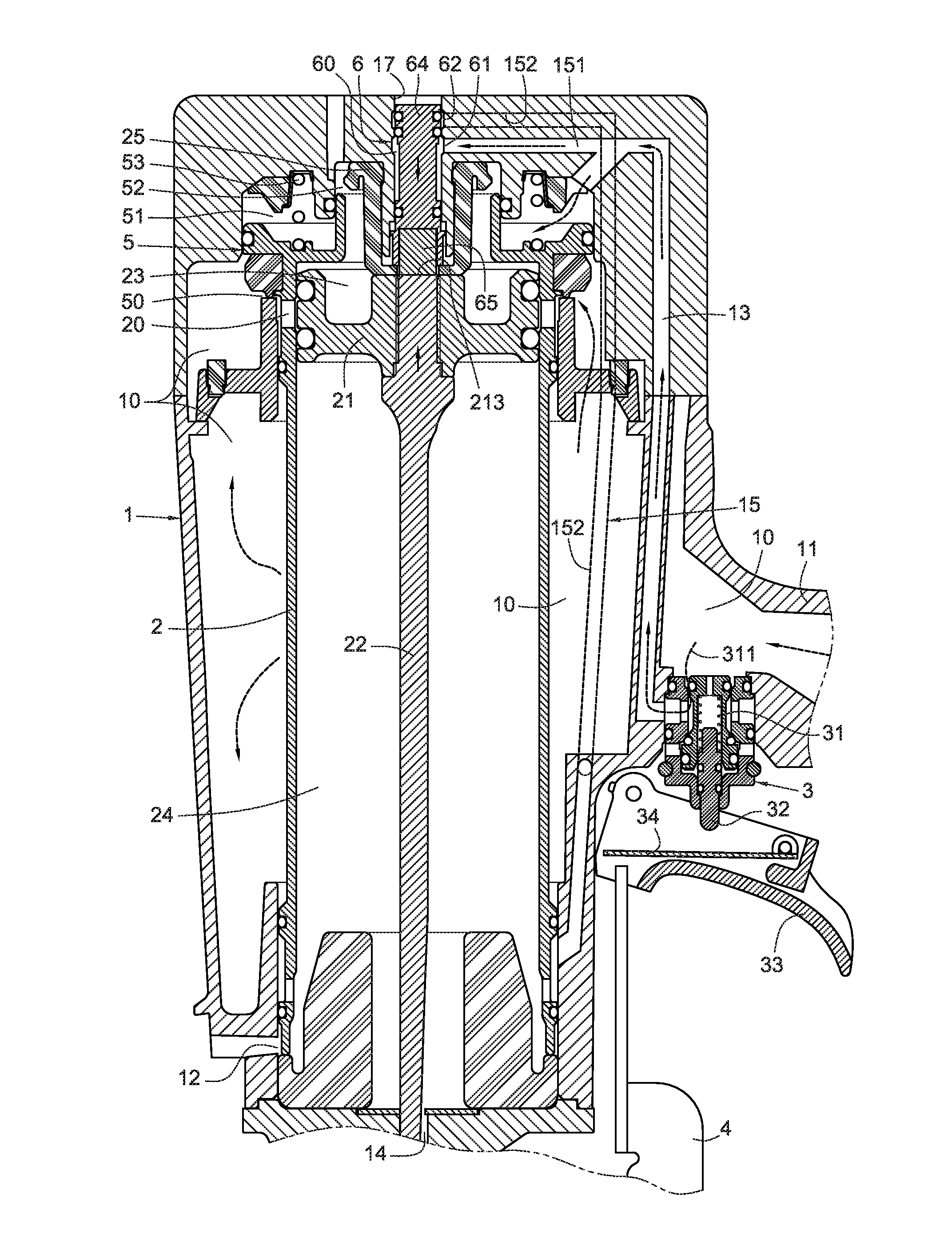
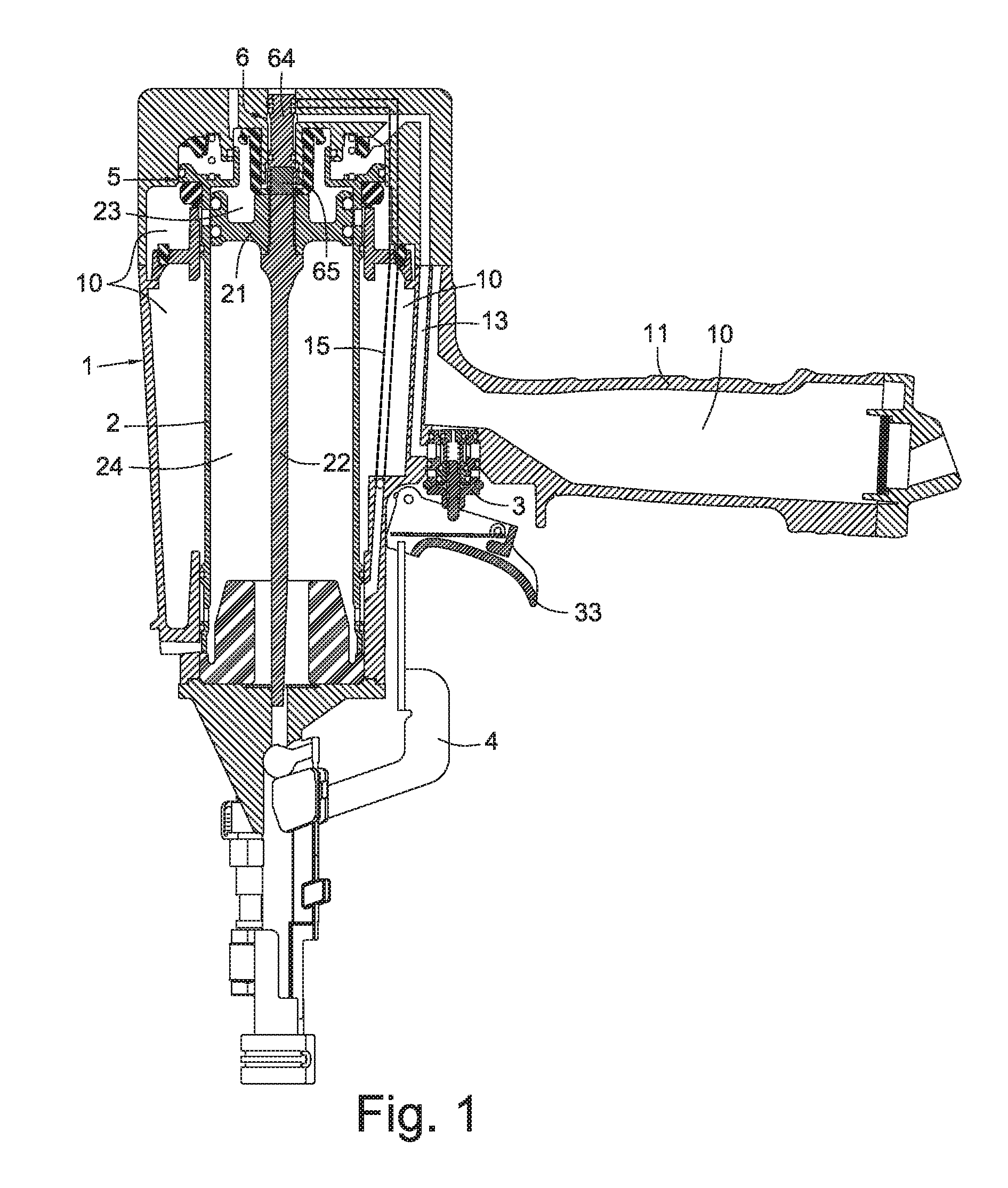
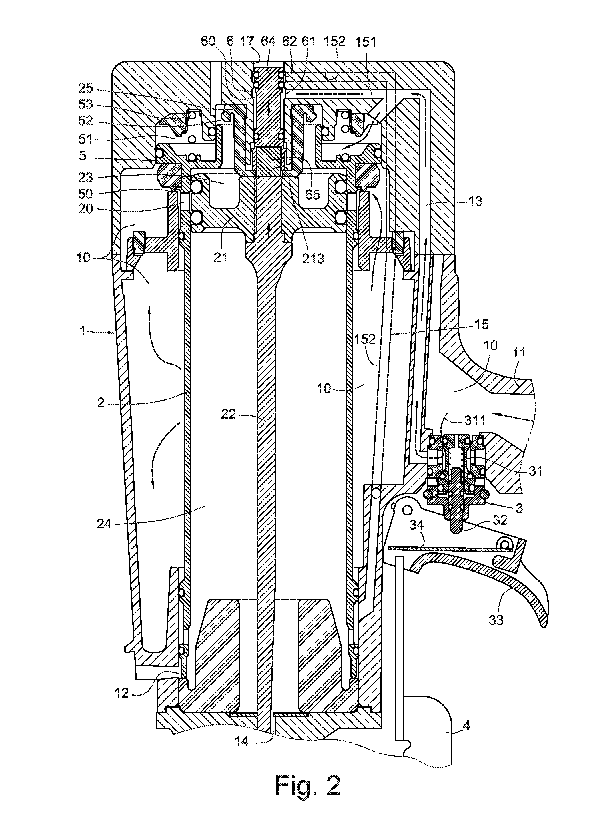
[0033]FIG. 1 and FIG. 2 are a cross-sectional view according to the present invention and a cross-sectional and partially enlarged view of the gun body of FIG. 1, respectively. They illustrate a nail-pushing rod restoring apparatus for a pneumatic nail gun. The nail-pushing rod restoring apparatus includes a piston 21 (which is set inside a gun body 1 of the pneumatic nail gun), a return air passage 15, and a magnetic valve 6. A cylinder 2 is set inside the gun body 1. In this embodiment, the cylinder 2 is a movable cylinder. The piston 21 is slidably mounted inside the cylinder 2. The piston 21's main body can be composed of magnetic metal (such as iron), forming an end surface 213 on the top of the piston 21 that is suitable for being lead by magnetic force. The bottom of the piston 21 is connected to a nail-pushing rod 22. The piston 21 divides the interior of the cylinder 2 into a top cylinder chamber 23 and a bottom cylinder chamber 24. Inside the gun body 1 there are several i...

second embodiment

[0049]FIG. 12 is a cross-sectional view according to the present invention, illustrating a nail-pushing rod restoring apparatus for a pneumatic nail gun. The nail-pushing rod restoring apparatus includes a magnetic piston 21a, a return air passage 15, and a valve 6a. The bottom of the magnetic piston 21a is connected to a nail pushing rod 22 (please refer to FIG. 2). The return air passage 15 is connected between the main air chamber 10 and the bottom cylinder chamber 24. The return air passage 15 also passes inside the gun body 1 above the cylinder 2. The valve 6a is disposed inside the gun body above the cylinder 2, and located on the return air passage 15 for controlling the open and close of the return air passage 15. The valve 6a's body can be composed of magnetic metal (such as iron). The bottom of the valve 6a forms an end surface 643a that is suitable for being lead by magnetic force. The end surface 643a is exposed inside the top cylinder chamber 23 and opposite to the top ...


PUM


Abstract

A nail-pushing rod restoring apparatus for a pneumatic nail gun includes a return air passage connected between a high-pressure main air chamber inside a gun body and a bottom cylinder chamber of a cylinder. A magnetic valve is disposed inside the gun body above the cylinder and located on the return air passage. An end of the magnetic valve is exposed inside a top cylinder chamber of the cylinder. The magnetic valve is lead by the piston to close the return air passage when the piston moves to the top of the cylinder. The magnetic valve is driven by the high-pressure air inside the top cylinder chamber to open the return air passage when the piston moves downward, so as to lead the high-pressure air inside the main air chamber to the bottom cylinder chamber to restore a nail-pushing rod after nail-pushing.

Description

BACKGROUND[0001]1. Technical Field[0002]The present invention relates to a nail-pushing rod restoring apparatus for a pneumatic nail gun. More particularly, the prevent invention relates to a nail-pushing piston inside the gun body of a nail gun and a valve for restoring the nail-pushing rod, where the valve and the piston may apply magnetic force on each other.[0003]2. Related Art[0004]Pneumatic nail gun is a handheld tool that uses high-pressure air as a source of momentum to perform nailing works. Generally speaking, outside the gun body there is a safety sliding rod, which can be pushed, for controlling nailing operation. Inside the gun body there are several main air chambers that can keep and concentrate high-pressure air at a constant pressure, a cylinder, a piston slidably mounted in the cylinder, a nail-pushing rod connecting to the bottom of the piston, and a trigger valve that drives the nail-pushing rod to pushing nails, etc. The piston divides the cylinder into a top cy...

Claims


Application Information

Patent Timeline
IPC IPC(8): B25C1/04
CPCB25C1/044
Inventor LIANG, CHIA-SHENGTSENG, CHU-HSIANG
Owner DE POAN PNEUMATIC
Why Eureka
Try Eureka