
Function based dynamic power control

Active Publication Date: 2012-04-26
ADVANCED MICRO DEVICES INC
View PDF39 Cites 98 Cited by
  • Summary
  • Abstract
  • Description
  • Claims
  • Application Information

AI Technical Summary

Benefits of technology

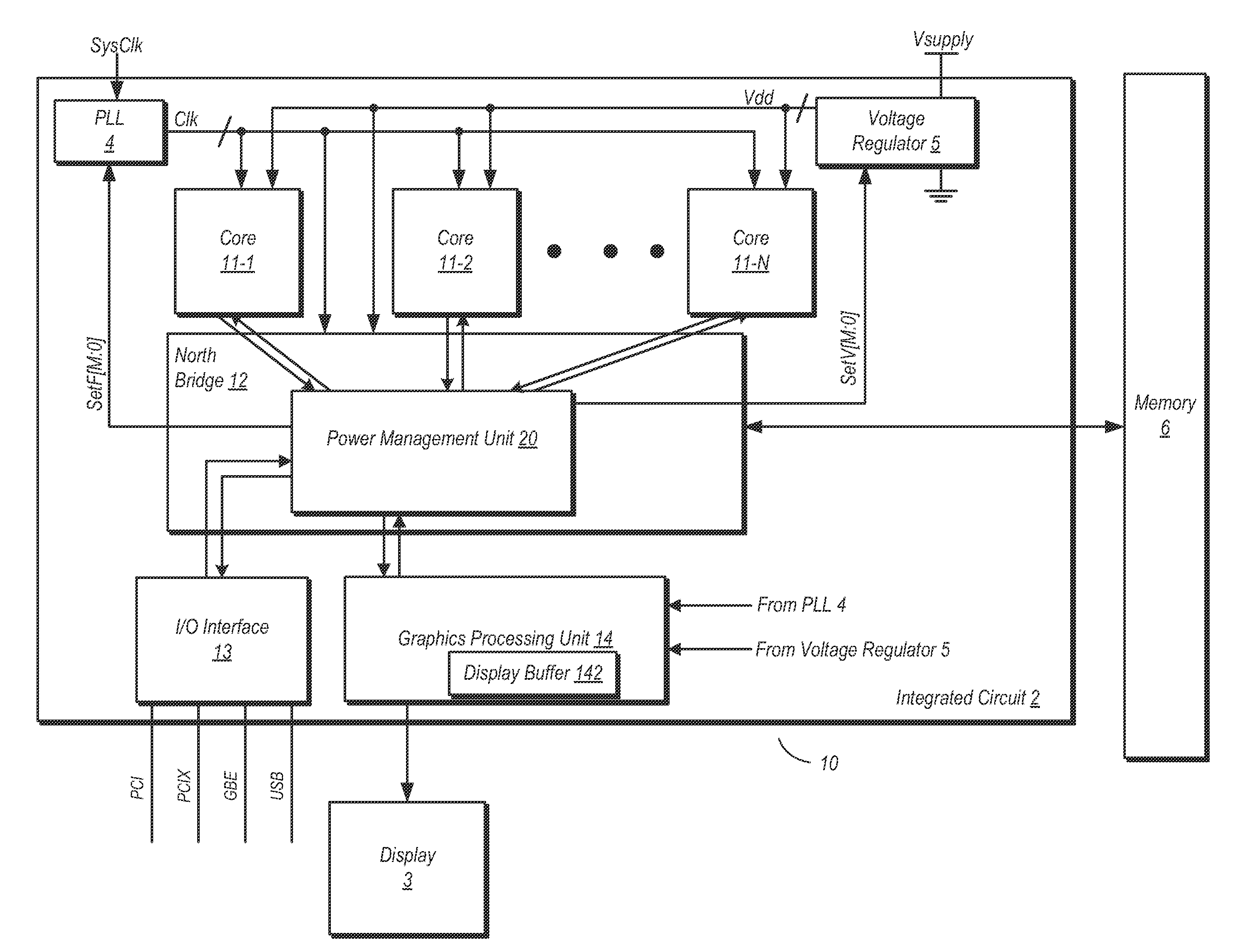
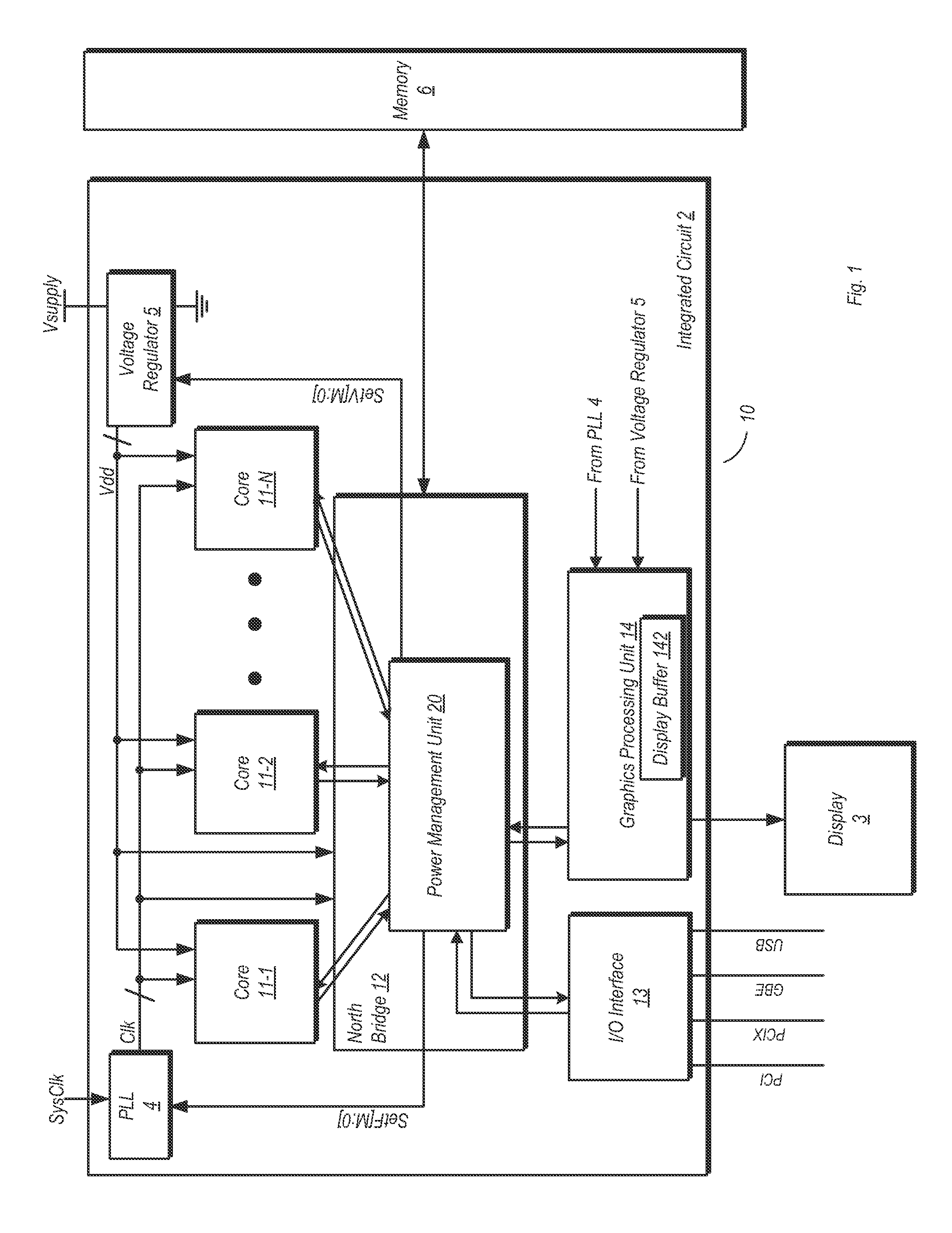
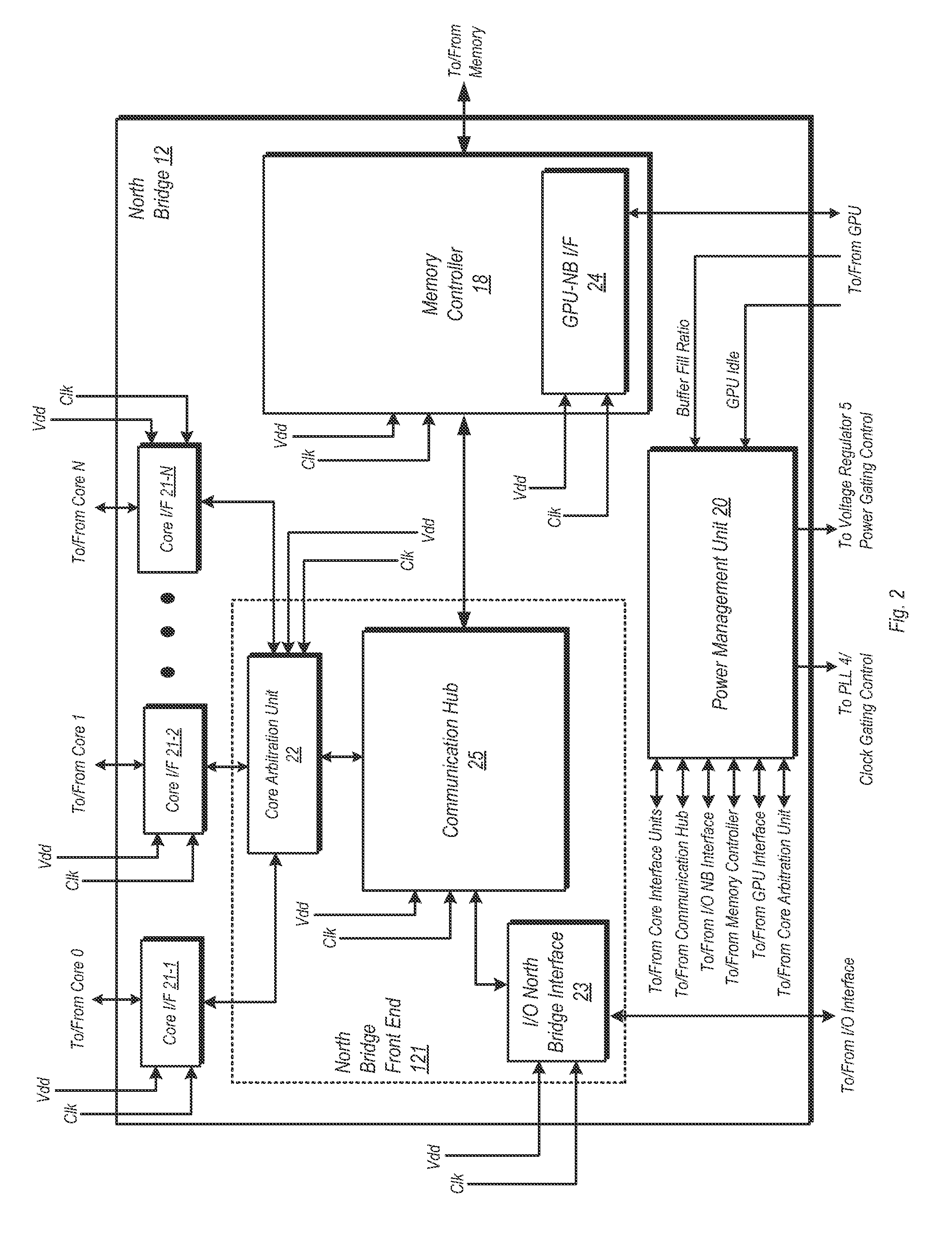
[0006]A system and method for dynamic function based power control is disclosed. In one embodiment, a system includes a bridge unit having a memory controller and a communication hub coupled to the memory controller. The system further includes a power management unit, wherein the power management unit is configured to clock-gate the communication hub responsive to determining that each of a plurality of processor cores are in an idle state and that an I/O interface unit has been idle for an amount of time exceeding a first threshold. The power management unit is further configured to clock-gate the memory controller responsive to clock-gating the communication hub and determining t

Problems solved by technology

A successful design may require several tradeoffs between power consumption, performance, thermal output, and so forth.
When using clock-gating, a clock signal provided to units of an IC may be inhibited or otherwise blocked from reaching those units when utilizing a power saving mode.

Method used


Image

  • Function based dynamic power control
  • Function based dynamic power control
  • Function based dynamic power control

Examples


Embodiment Construction

[0006]A system and method for dynamic function based power control is disclosed. In one embodiment, a system includes a bridge unit having a memory controller and a communication hub coupled to the memory controller. The system further includes a power management unit, wherein the power management unit is configured to clock-gate the communication hub responsive to determining that each of a plurality of processor cores are in an idle state and that an I / O interface unit has been idle for an amount of time exceeding a first threshold. The power management unit is further configured to clock-gate the memory controller responsive to clock-gating the communication hub and determining that a memory coupled to the memory controller is in a first low power state. The power management unit may also perform power-gating of functional units subsequent to clock-gating the same.

[0007]In one embodiment, a method includes clock-gating a communication hub of a bridge unit responsive to determinin...


PUM


Abstract

A system and method for dynamic function based power control is disclosed. In one embodiment, a system includes a bridge unit having a memory controller and a communication hub coupled to the memory controller. The system further includes a power management unit, wherein the power management unit is configured to clock-gate the communication hub responsive to determining that each of a plurality of processor cores are in an idle state and that an I / O interface unit has been idle for an amount of time exceeding a first threshold. The power management unit is further configured to clock-gate the memory controller responsive to clock-gating the communication hub and determining that a memory coupled to the memory controller is in a first low power state. The power management unit may also perform power-gating of functional units subsequent to clock-gating the same.

Description

BACKGROUND[0001]1. Field of the Invention[0002]This invention relates to integrated circuits (IC's), and more particularly, to controlling the power consumption of IC's.[0003]2. Description of the Related Art[0004]During the design of a computer or other processor-based system, many design factors must be considered. A successful design may require several tradeoffs between power consumption, performance, thermal output, and so forth. For example, the design of a computer system with an emphasis on high performance may allow for greater power consumption and thermal output. Conversely, the design of a portable computer system that is sometimes powered by a battery may emphasize reducing power consumption at the expense of some performance. These same factors may be considered when designing the individual IC's to be used in the computer system.[0005]Two commonly used methods of controlling power consumption are clock-gating and power-gating. When using clock-gating, a clock signal p...

Claims


Application Information

Patent Timeline
IPC IPC(8): G06F1/00
CPCG06F1/3237G06F1/3275G06F1/3287Y02B60/1221Y02B60/1228Y02B60/1282Y02B60/32Y02D10/00Y02D30/50
Inventor KOCEV, ANDREJBRANOVER, ALEXANDER
Owner ADVANCED MICRO DEVICES INC
Learn More