Use of auxiliary rudders for yaw control at low speed
Active Publication Date: 2012-05-03
NEW HOLBORN LTD +1
View PDF36 Cites 20 Cited by
Summary
Abstract
Description
Claims
Application Information
AI Technical Summary
This helps you quickly interpret patents by identifying the three key elements:
Problems solved by technology
Method used
Benefits of technology
[0021]In another aspect of the invention, the fan includes inner blades and outer blades, positioned radially outwardly from the inner blades. A ring extends circumferentially around the inner blades and is positioned radially between the inner blades and outer blades. Th
Problems solved by technology
In an emergency landing when an autogyro has lost power, the airspeed of the autogyro is likely to be low due to a lack of propulsion.
However, yaw control is not readily accom
Method used
Image
Click on the blue label to locate the original text in one second.
Reading with bidirectional positioning of images and text.
Examples
Example
[0054]It will be readily understood that the components of the present invention, as generally described and illustrated in the drawings herein, could be arranged and designed in a wide variety of different configurations. Thus, the following more detailed description of the embodiments of the system and method of the present invention, as represented in the drawings, is not intended to limit the scope of the invention, as claimed, but is merely representative of various embodiments of the invention. The illustrated embodiments of the invention will be best understood by reference to the drawings, wherein like parts are designated by like numerals throughout.
[0055]This patent application hereby incorporates by reference U.S. Pat. No. 5,301,900 issued Apr. 12, 1994 to Groen et al., U.S. Pat. No. 1,947,901 issued Feb. 20, 1934 to J. De la Cierva, and U.S. Pat. No. 2,352,342 issued Jun. 27, 1944 to H. F. Pitcairn.
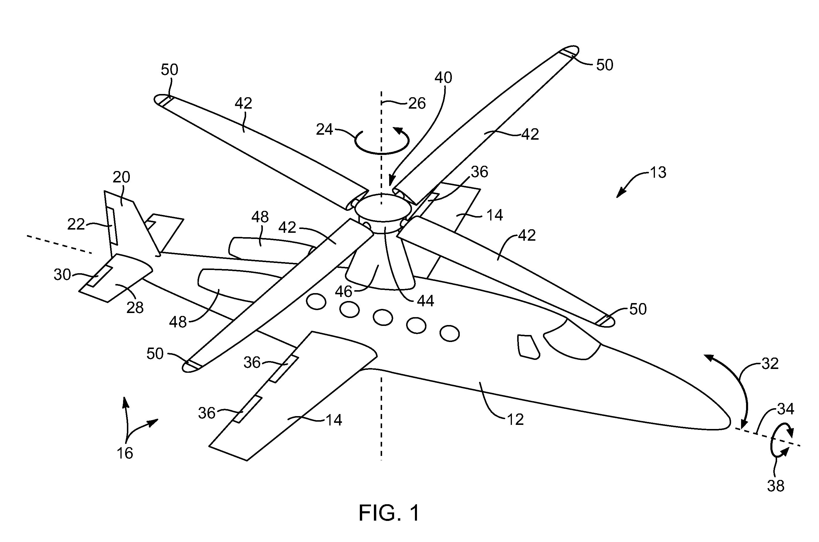
[0056]Referring to FIG. 1, an aircraft 10 includes a fuselage 12 defining...
PUM
Abstract
Apparatus and methods for controlling yaw of a rotorcraft in the event of one or both of low airspeed and engine failure are disclosed. A yaw propulsion provides a yaw moment at low speeds. The yaw propulsion device may be an air jet or a fan. A pneumatic fan may be driven by compressed air released into a channel surrounding an outer portion of the fan. The fan may be driven by hydraulic power. Power for the yaw propulsion device and other system may be provided by a hydraulic pump and/or generator engaging the rotor. Low speed yaw control may be provided by auxiliary rudders positioned within the stream tube of a prop. The auxiliary rudders may one or both of fold down and disengage from rudder controls when not in use.
Description
RELATED APPLICATIONS[0001]This application claims the benefit of co-pending U.S. patent application Ser. No. 13 / 199,671, filed on Sep. 7, 2011, which claims the benefit of U.S. Provisional Patent Application Ser. No. 61 / 381,291, filed on Sep. 9, 2010, co-pending U.S. patent application Ser. No. 13 / 199,684, filed on Sep. 7, 2011, which claims the benefit of U.S. Provisional Patent Application Ser. No. 61 / 403,099, filed on Sep. 9, 2010, co-pending U.S. patent application Ser. No. 13 / 199,678, filed on Sep. 7, 2011, which claims the benefit of U.S. Provisional Patent Application Ser. No. 61 / 403,097, filed on Sep. 9, 2010, co-pending U.S. patent application Ser. No. 13 / 199,682, filed on Sep. 7, 2011, which claims the benefit of U.S. Provisional Patent Application Ser. No. 61 / 381,313, filed on Sep. 9, 2010, co-pending U.S. patent application Ser. No. 13 / 199,681, filed on Sep. 7, 2011, which claims the benefit of U.S. Provisional Patent Application Ser. No. 61 / 403,111, filed on Sep. 9, 201...
Claims
Application Information
Patent Timeline
Application Date:The date an application was filed.
Publication Date:The date a patent or application was officially published.
First Publication Date:The earliest publication date of a patent with the same application number.
Issue Date:Publication date of the patent grant document.
PCT Entry Date:The Entry date of PCT National Phase.
Estimated Expiry Date:The statutory expiry date of a patent right according to the Patent Law, and it is the longest term of protection that the patent right can achieve without the termination of the patent right due to other reasons(Term extension factor has been taken into account ).
Invalid Date:Actual expiry date is based on effective date or publication date of legal transaction data of invalid patent.