Illumination device comprising an internal power source and an interface for connecting the illumination device to an external power supply

an illumination device and power supply technology, which is applied in the direction of semiconductor devices, lighting and heating apparatus, and with built-in power, can solve the problem of not exceeding the maximum luminance of the illumination device when powered via an external power supply, such as the mains supply, rather than being limited by. the problem of overheating, to achieve the effect of enhancing heat dissipation, efficient and reliable way, and preventing overheating

Inactive Publication Date: 2012-05-03
KONINKLIJKE PHILIPS ELECTRONICS NV
View PDF13 Cites 5 Cited by
  • Summary
  • Abstract
  • Description
  • Claims
  • Application Information

AI Technical Summary

Benefits of technology

[0012]The circuitry may also be configured to enable charging of the internal power source when the illumination device is electrically connected to the external power supply. An advantage associated herewith is that the internal power source can be charged without being removed from the illumination device.
[0013]According to an embodiment, the electrical interface may be configured to transfer electrical energy via direct electrical contact, thereby providing an efficient and reliable way to transfer electricity between the external power supply and the illumination device.
[0014]Furthermore, the electrical interface and the thermal interface may be arranged in a plug adapted to be received in a corresponding socket in an interfacing device. As the electrical interface and the thermal interface are both integrated in the plug it can be ensured that when the illumination device is connected to the external power supply it will also be connected to the external heat sink, and thus overheating may efficiently be prevented.
[0015]According to another aspect of the invention, there is provided an interfacing device comprising: a power sup

Problems solved by technology

This is because, the maximum luminance when the illumination device is powered by the internal power source, primarily is limited by the capacity of the internal power source, whereas

Method used


Image

  • Illumination device comprising an internal power source and an interface for connecting the illumination device to an external power supply
  • Illumination device comprising an internal power source and an interface for connecting the illumination device to an external power supply
  • Illumination device comprising an internal power source and an interface for connecting the illumination device to an external power supply

Examples


Embodiment Construction

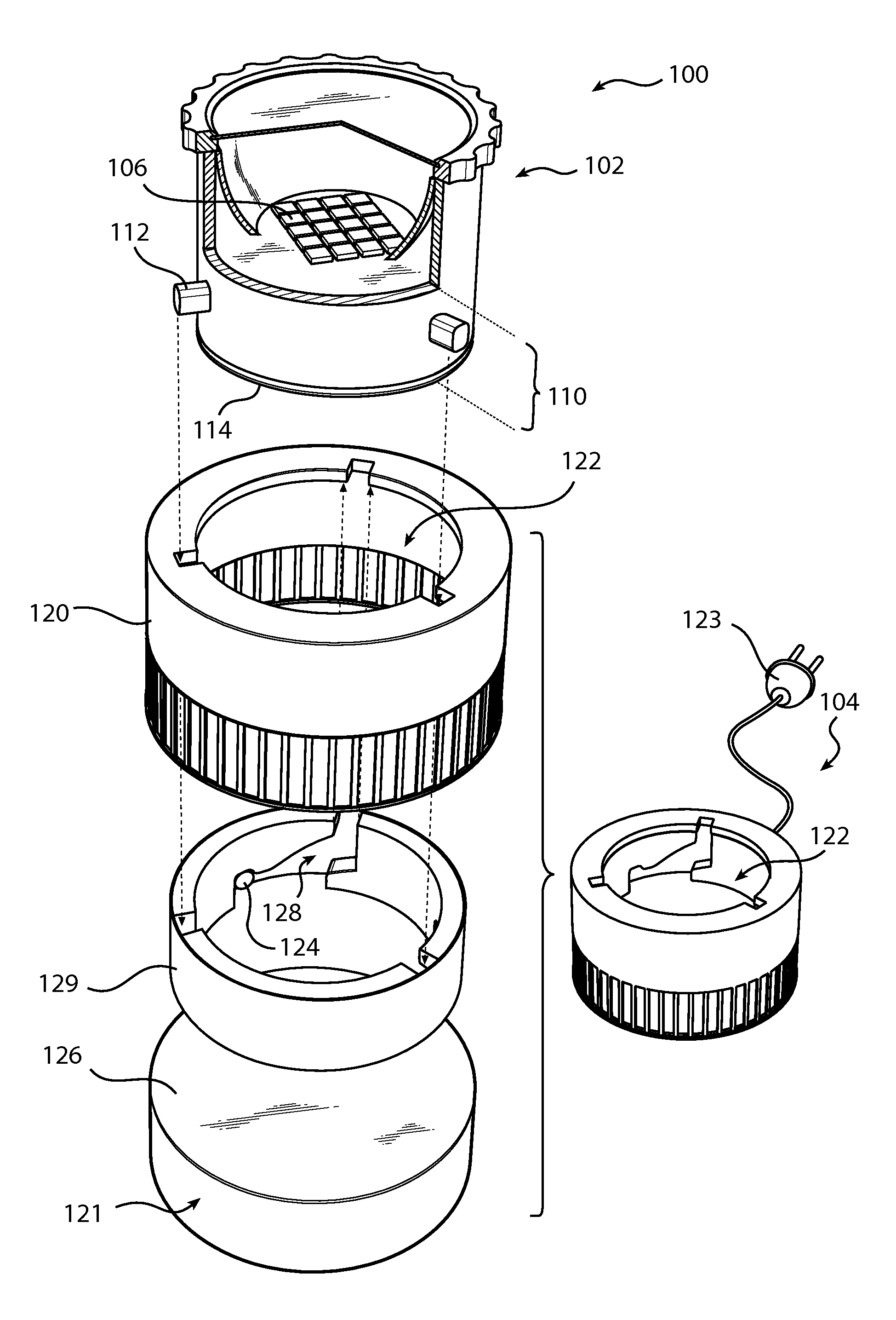
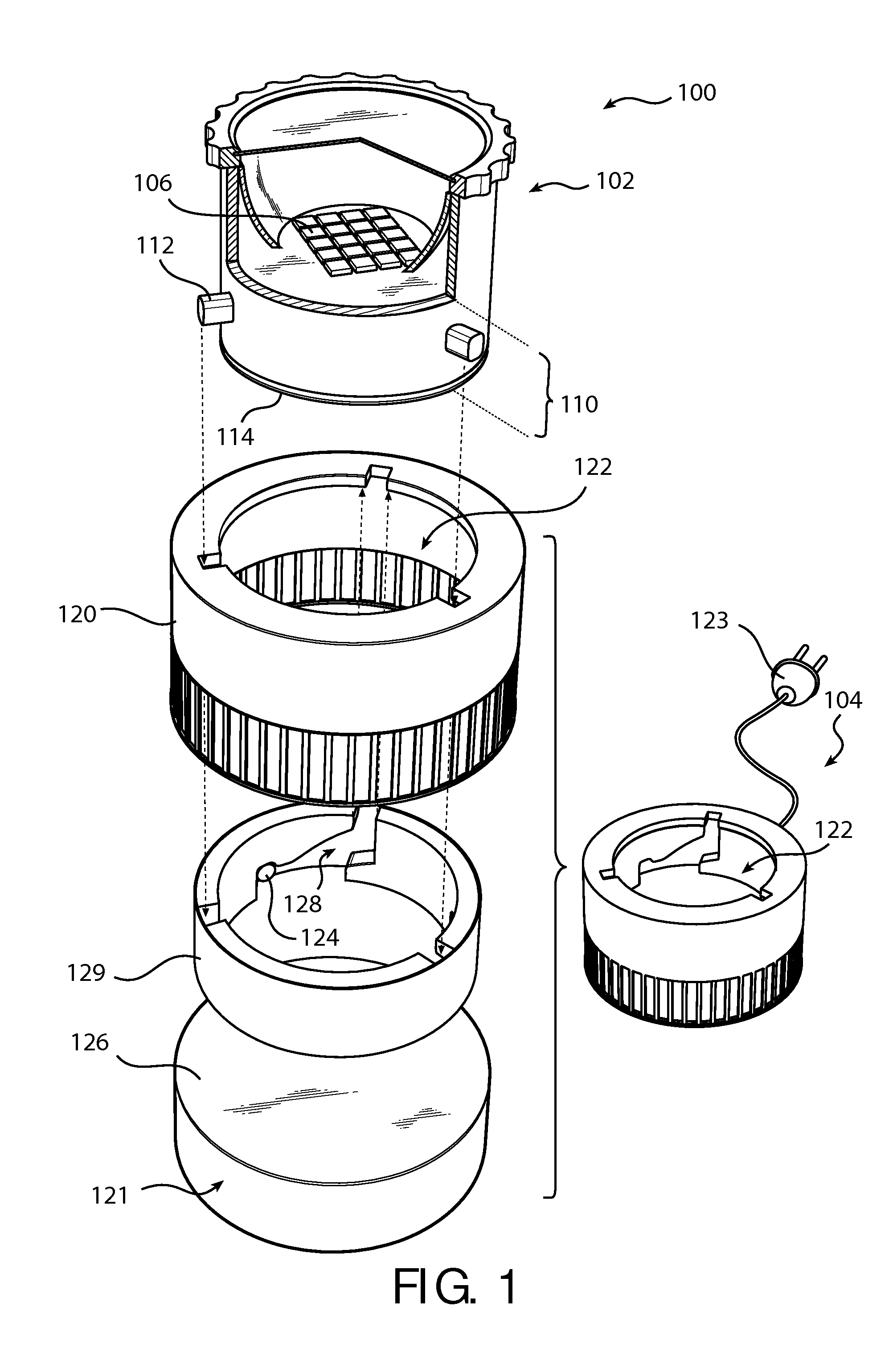
[0023]FIG. 1 schematically illustrates an illumination system according to an embodiment of the invention. The illumination system 100 comprises an illumination device 102, and an interfacing device 104, here being a charger.

[0024]The illumination device is here a movable lamp dimensioned such that a user can pick-up the illumination device and place it at a desired location. Thus, a user may e.g. take the illumination device out of the charger and place it at a table next to his chair as a reading lamp. The illustrated illumination device has a diameter about 80 mm and height about 60 mm. However, as is recognized by a person skilled in the art the size of the illumination device may vary.

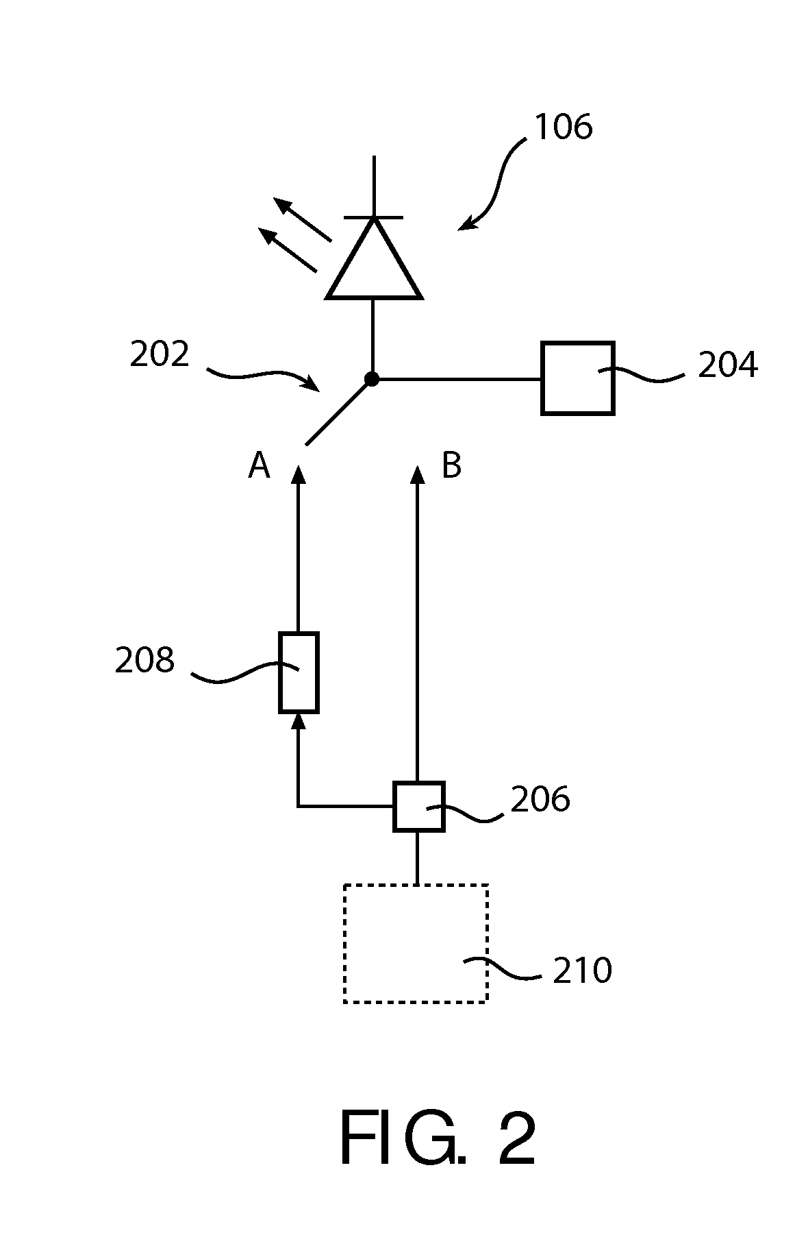
[0025]The illumination device 102 comprises a plurality light emitting devices 106, here being light emitting diodes (LEDs) 106 arranged on a printed circuit board. The number of LEDs will vary depending on the application, but is typically selected based on the amount of heat that can be dissipat...


PUM


Abstract

An illumination device comprising: at least one light emitting device (106); an internal power source (208); an electrical interface (112) for electrically connecting said illumination device to an external power supply (210); a thermal interface (114) for thermally connecting said illumination device to an external heat sink (121); and a circuitry for operating said illumination device in a first mode when disconnected from at least one of said external power supply (210) and said external heat sink (121), in which first mode said at least one light emitting device (106) is powered by said internal power source (208), and in a second mode when said illumination device is connected to said external power supply (210) and said external heat sink (121), in which second mode said at least one light emitting device (106) is powered by said external power supply (210), and wherein a first maximum luminance in said first mode is restricted relative a second maximum luminance in said second mode.

Description

TECHNICAL FIELD[0001]The present invention relates to an illumination device comprising an internal power source and an electrical interface for electrically connecting the illumination device to an external power supply. It also relates to an interfacing device that provides an external power supply, and to a system comprising such an illumination device and such an interfacing device.BACKGROUND OF THE INVENTION[0002]A movable lamp may be convenient in situations where there are no luminaires available or where the illumination from the available luminaires is insufficient.[0003]If the movable lamp is used where there is no electricity available from the mains supply, the movable lamp must be powered by an internal power source, such as a battery. However, due to the limited power available from a battery, it is often preferred to power the movable lamp via the mains supply when possible.[0004]A prior art arrangement that can be used in both situations would be an illumination syst...

Claims


Application Information

Patent Timeline
IPC IPC(8): F21L4/00F21Y101/00
CPCF21S6/004F21S9/02F21V17/14F21V19/04F21V29/004F21V29/74F21Y2105/10F21Y2115/10F21V29/70F21V29/00
Inventor TREURNIET, THEODOOR CORNELIS
Owner KONINKLIJKE PHILIPS ELECTRONICS NV
Why Eureka
Try Eureka