Connector for connecting a component to a heat sink

a technology for connecting components and heat sinks, which is applied in fixed installation, lighting and heating apparatus, and lighting support devices. it can solve problems such as leds showing early failures and the need to replace the entire fixture, and achieve the effect of efficient heat dissipation

Active Publication Date: 2012-05-03
KONINKLIJKE PHILIPS ELECTRONICS NV
View PDF13 Cites 56 Cited by
  • Summary
  • Abstract
  • Description
  • Claims
  • Application Information

AI Technical Summary

Benefits of technology

[0006]It is an object of the present invention to provide a connector for releasably c...

Problems solved by technology

Thus, most fixture designs are such that if the light source fails, the entire fixture needs to be replaced.
However, just as other types of light sources, LEDs may show early failures.
However, sometimes the pr...

Method used


Image

  • Connector for connecting a component to a heat sink
  • Connector for connecting a component to a heat sink
  • Connector for connecting a component to a heat sink

Examples


Embodiment Construction

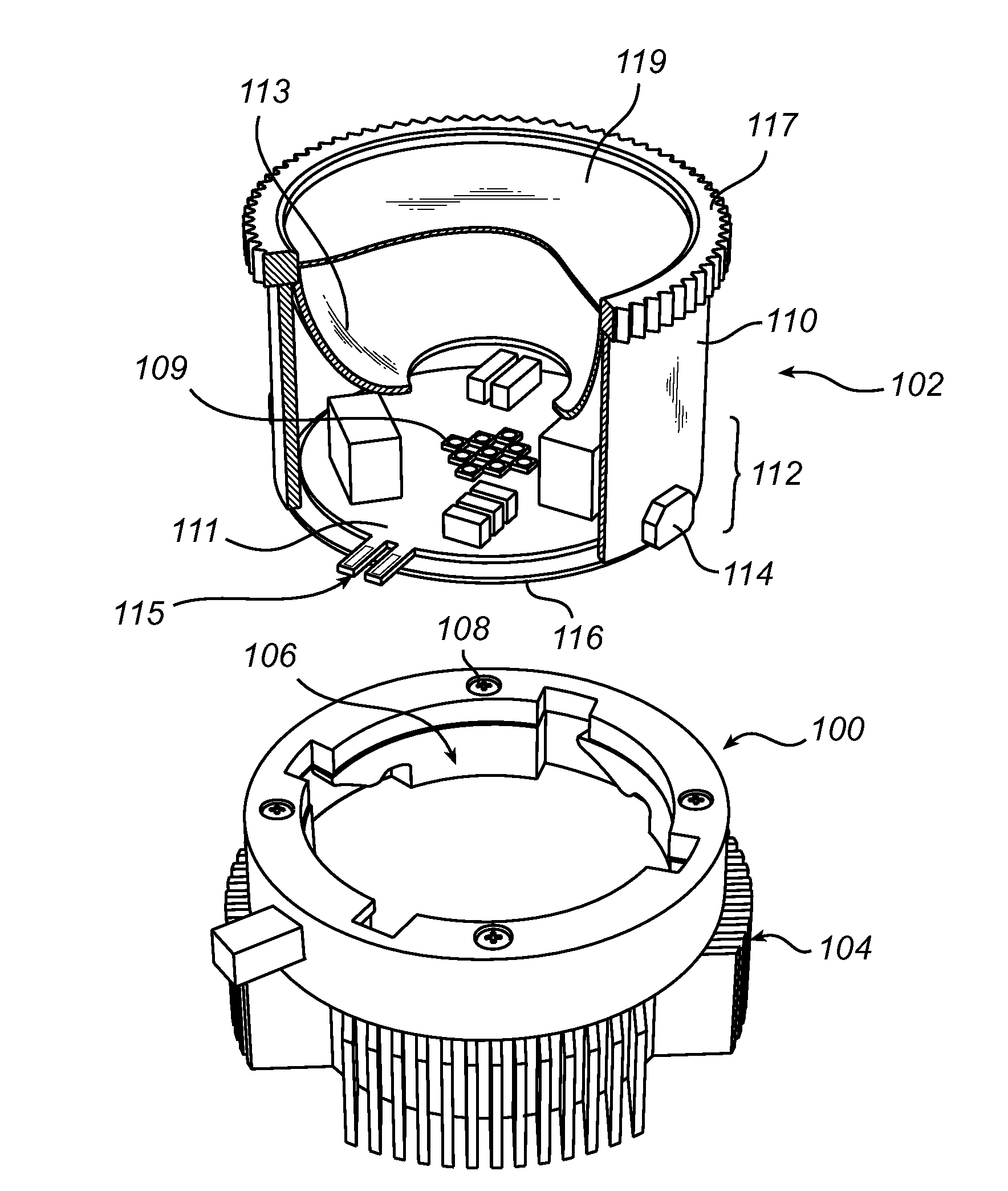
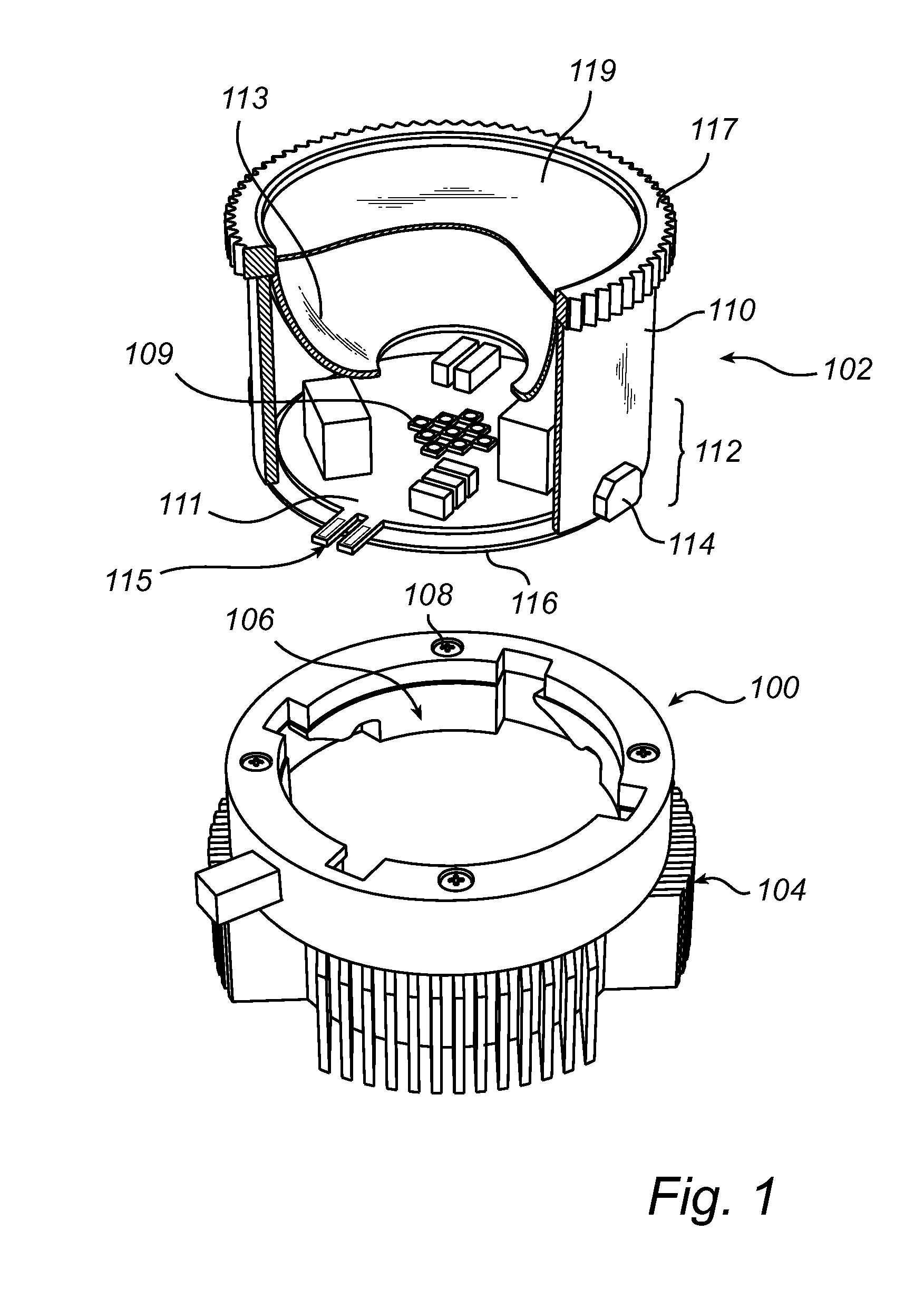
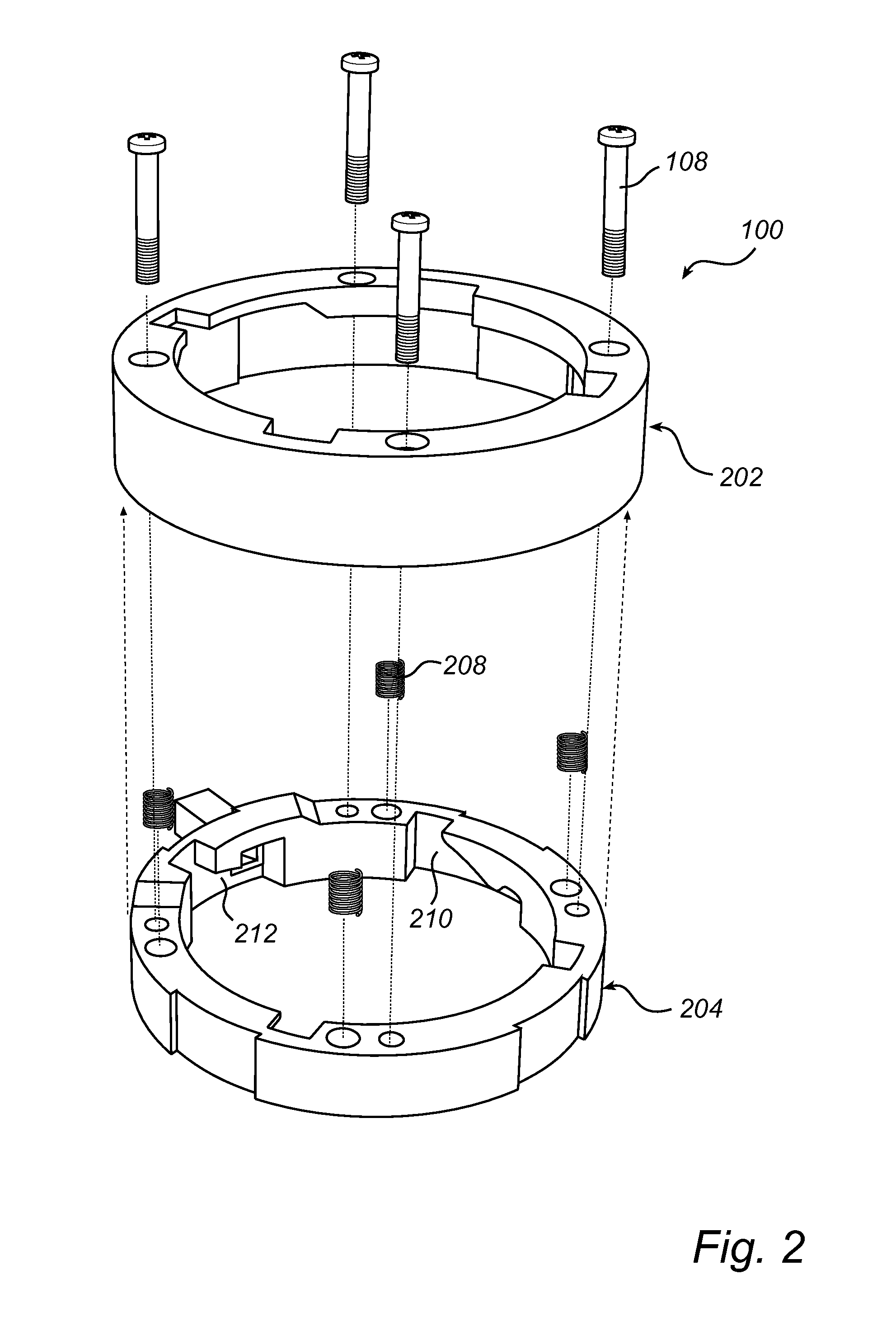
[0033]FIG. 1 schematically illustrates a connector 100 for connecting a lighting module 102 to a heat sink 104. The connector (here referred to as a lamp holder 100) is formed as a receiving part of a bayonet coupling enclosing a circular opening 106 for receiving the lighting module 102. The lamp holder 100 is here mounted to the heat sink 104 by screws 108. Thus, as the lighting module 102 is connected to the lamp holder 100, a thermal interface 116 of the lighting module (provided at the bottom of the lighting module) is in direct contact with the heat sink 104, thereby enabling heat dissipation from the lighting module 102 to the heat sink 104.

[0034]The lighting module 102 (here referred to as an LED module 102) comprises a cylindrical housing comprising a bottom surface 116, a side wall 110, and a top surface 119. The top surface is here a phosphor disc 119 for allowing light from the LED module to escape. The housing contains a plurality light emitting devices 109, here being ...


PUM


Abstract

A connector (100) for connecting a component (102) to a heat sink (104), wherein the connector (100) is formed as a female part of a bayonet coupling enclosing an opening (106) for receiving one of the component (102) and the heat sink (104). Further, the connector (100) in use is arranged to ensure direct thermal contact between the component (102) and the heat sink (104) in the opening (106).

Description

FIELD OF THE INVENTION[0001]The present invention relates to a connector for connecting a component to a heat sink.BACKGROUND OF THE INVENTION[0002]In many applications it may desirable to connect a component to a heat sink to provide enhanced heat dissipation. This may be applicable, for example, in general lighting applications that use light emitting diodes (LEDs).[0003]The dominating conception in the market today seems to be that LEDs “last forever”, or at least about 50 000 hours, and do not break down prematurely. Thus, most fixture designs are such that if the light source fails, the entire fixture needs to be replaced. However, just as other types of light sources, LEDs may show early failures. In addition, in some applications (e.g. shops, restaurants, bars), the refurbishment cycles are much shorter than the specified LED lifetime of 50 000 hours, whereas in other applications (e.g. outdoor, street, office, and hospital), the LED lifetime is shorter than the refurbishment...

Claims


Application Information

Patent Timeline
IPC IPC(8): F21V17/14F21V29/00
CPCF21V17/14F21V19/001F21V19/045F21V29/745F21V29/763F21V23/06F21V29/74F21V29/71F21V29/70F21Y2115/10F21S8/026F21V19/04F21K9/20F21K9/00F21Y2101/00
Inventor BLANKESTIJN, JAN-IVODEURENBERG, PETER HUBERTUS FRANCISCUSKESER, MERIJNCOOIJMANS, HUIBVISSENBERG, MICHEL CORNELIS JOSEPHUS MARIE
Owner KONINKLIJKE PHILIPS ELECTRONICS NV
Why Eureka
Try Eureka