
Payload launch lock mechanism

a payload and lock technology, applied in the direction of cosmonautic components, cosmonautic parts, cosmonautic vehicles, etc., can solve the problems of affecting the flight of the payload, the bolt may transmit relatively high loads from high frequency acceleration, and the payload may be damaged, so as to achieve the effect of expanding the payload range of motion

Active Publication Date: 2012-05-10
HONEYWELL INT INC
View PDF2 Cites 28 Cited by
  • Summary
  • Abstract
  • Description
  • Claims
  • Application Information

AI Technical Summary

Benefits of technology

[0030]The payload launch lock mechanisms 100, 500, 900 disclosed herein will sufficiently restrain a payload 112 during launch and, due to the rotating or pivoting nature of the preload clamps 104, allow subsequent release of the payload 112 without transmitting relatively high loads to the payload 112, and with larger payload ranges of motion than known mechanisms that do not have rotating or pivoting mechanisms.

Problems solved by technology

During spacecraft launch, relatively large vibration and thrust loads may be imparted on the payloads.
For example, breaking the bolt may transmit relatively high loads from high frequency acceleration (e.g., shock) to the payload.
This can potentially cause damage to the payload.
Current state of the art approaches for such devices have limited dynamic ranges, and therefore result in the payload having a limited range of motion allowable, due to the specific implementation details.

Method used


Image

  • Payload launch lock mechanism
  • Payload launch lock mechanism
  • Payload launch lock mechanism

Examples


Embodiment Construction

[0021]The following detailed description is merely exemplary in nature and is not intended to limit the invention or the application and uses of the invention. As used herein, the word “exemplary” means “serving as an example, instance, or illustration.” Thus, any embodiment described herein as “exemplary” is not necessarily to be construed as preferred or advantageous over other embodiments. All of the embodiments described herein are exemplary embodiments provided to enable persons skilled in the art to make or use the invention and not to limit the scope of the invention which is defined by the claims. Furthermore, there is no intention to be bound by any expressed or implied theory presented in the preceding technical field, background, brief summary, or the following detailed description.

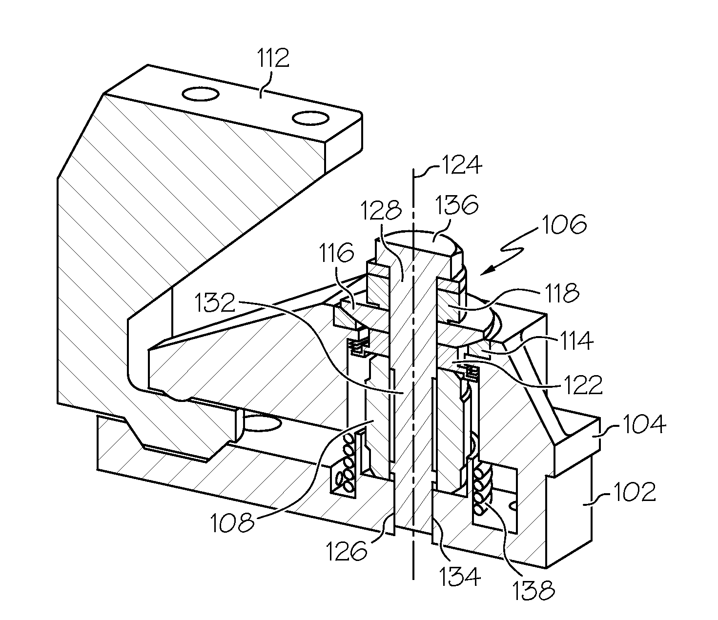
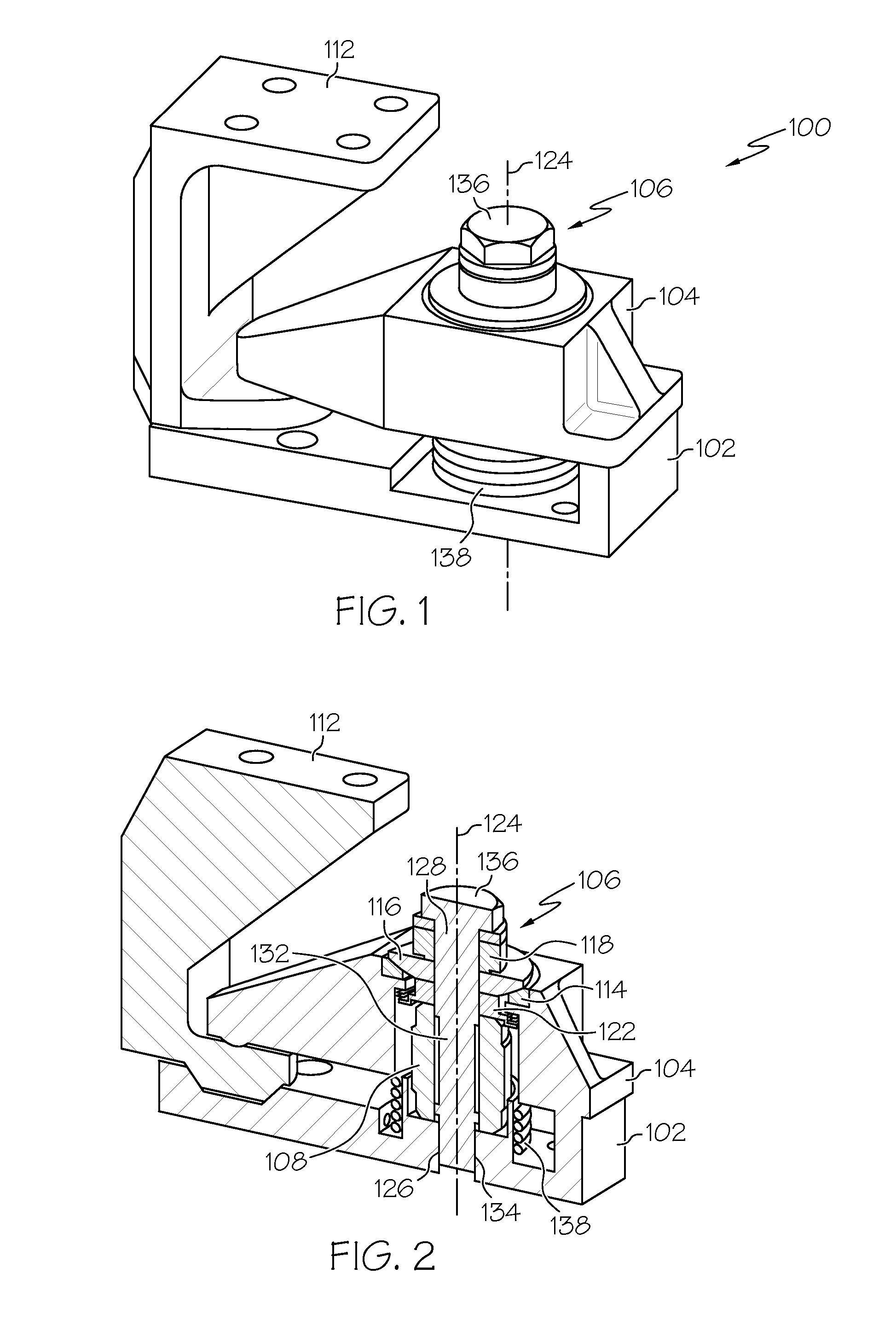
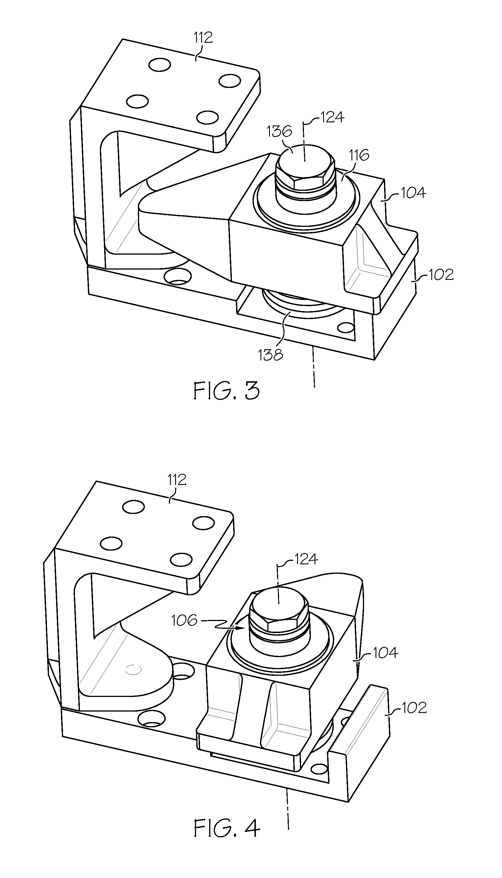
[0022]Referring now to FIGS. 1 and 2, one embodiment of a payload launch lock mechanism 100 is depicted and includes a base 102, a preload clamp 104, a fastener 106, and a shape memory alloy (S...


PUM


Abstract

A payload launch lock mechanism includes a base, a preload clamp, a fastener, and a shape memory alloy (SMA) actuator. The preload clamp is configured to releasibly restrain a payload. The fastener extends, along an axis, through the preload clamp and into the base, and supplies a force to the preload clamp sufficient to restrain the payload. The SMA actuator is disposed between the base and the clamp. The SMA actuator is adapted to receive electrical current and is configured, upon receipt of the electrical current, to supply a force that causes the fastener to elongate without fracturing. The preload clamp, in response to the fastener elongation, either rotates or pivots to thereby release the payload.

Description

STATEMENT REGARDING FEDERALLY SPONSORED RESEARCH OR DEVELOPMENT[0001]This invention was made with Government support under NNG09HR00C awarded by NASA. The Government has certain rights in this invention.TECHNICAL FIELD[0002]The present invention generally relates to releasable locks for spacecraft payloads, and more particularly relates to a pivoting payload launch lock.BACKGROUND[0003]Many spacecraft include one or more payloads that are released after the spacecraft attains orbit. During spacecraft launch, relatively large vibration and thrust loads may be imparted on the payloads. Thus, payloads are typically mounted on the spacecraft using launch lock devices that are configured to both restrain the payloads against these vibration and thrust loads, and to subsequently release the payloads when the spacecraft attains orbit.[0004]Commonly used launch lock devices are configured to release a payload by breaking a bolt using either pyrotechnics or a shape memory alloy (SMA). While ...

Claims


Application Information

Patent Timeline
Patent Type & Authority Applications(United States)
IPC IPC(8): B64G1/22B64G99/00
CPCB64G1/641B64G1/642
Inventor YOUNG, KENHINDLE, TIMOTHY
Owner HONEYWELL INT INC
Learn More