
Low power device and method for livestock detection

a low-power device and livestock technology, applied in the field of low-power devices and methods for livestock detection, can solve the problems of high power consumption of devices attached to animals, high power consumption of such devices attached to animals during communication, and high power consumption of such devices

Active Publication Date: 2012-05-10
SCR ENGINEERS LTD
View PDF7 Cites 14 Cited by
  • Summary
  • Abstract
  • Description
  • Claims
  • Application Information

AI Technical Summary

Benefits of technology

[0008]In accordance with one aspect of the present exemplary embodiment, the present application is a series of RFID transponders and receiving devices for tracking barnyard animals. The system involves electronic tags attached to the bodies of livestock. The signals are picked up by a receiver attached to a stationary platform, or located in a vehicle, or in a portable hand held receiver device. The information transmitted can be used to locate a specific animal or can be used to monitor the status and condition of the animal. The device contains several modes which minimize power consumption and maximize power supply lifetime.

Problems solved by technology

Such a system requires high power consumption from the device attached to the animal during communication and also requires line of sight between the animal and the satellites.
Other disclosures based on absolute pinpoint of an animal's location in a predefined coordinate system requires an expensive pre-installed array of antennas in the farm.
The power consumption of such devices attached to the animal during communication is high because the device must transmit data for periods of minutes in order to enable accurate tracking.
Such devices do not contain a battery and theoretically have an endless lifespan.
Such devices can be detected from only a very short range, such as, less than 1 m and can only find an animal confined to a very narrow space or passage.
Such a device must have a very long life span because attaching the device to an animal is a very time consuming and tedious job.

Method used


Image

  • Low power device and method for livestock detection
  • Low power device and method for livestock detection
  • Low power device and method for livestock detection

Examples


Embodiment Construction

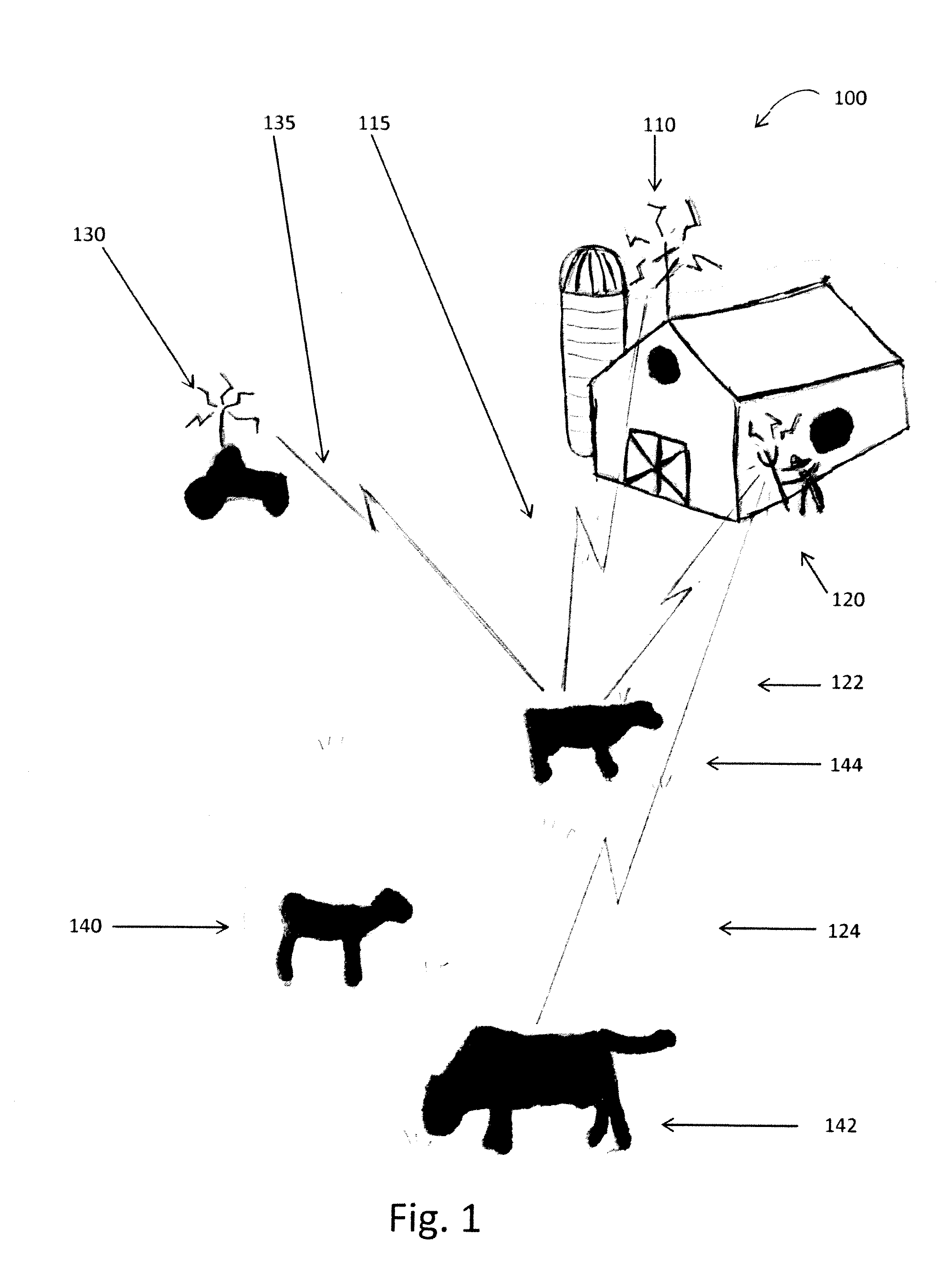
[0013]FIG. 1 illustrates the concept presented in the current application 100. One object of the present invention to provide a novel, low power consuming device for attachment to a farm animal 140, 142, 144 which may be able to receive and transmit signals 115, 122, 124, 135 to and from remote receivers and / or transmitters. While the present application is directed toward farm animals such as but not limited to cows, bulls, steers, cattle, horses, goats, pigs, sheep, llamas, alpacas, chickens, hens, roosters, turkeys and any other birds, the present application may easily be applied to zoo animals such as elephants, rhinos, giraffes, or animals residing in the wild such as tigers, lions and bears.

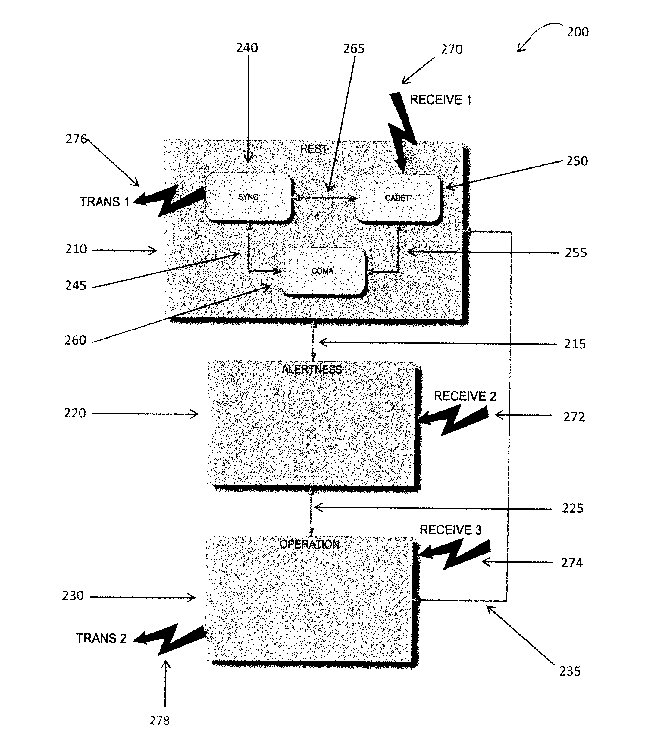
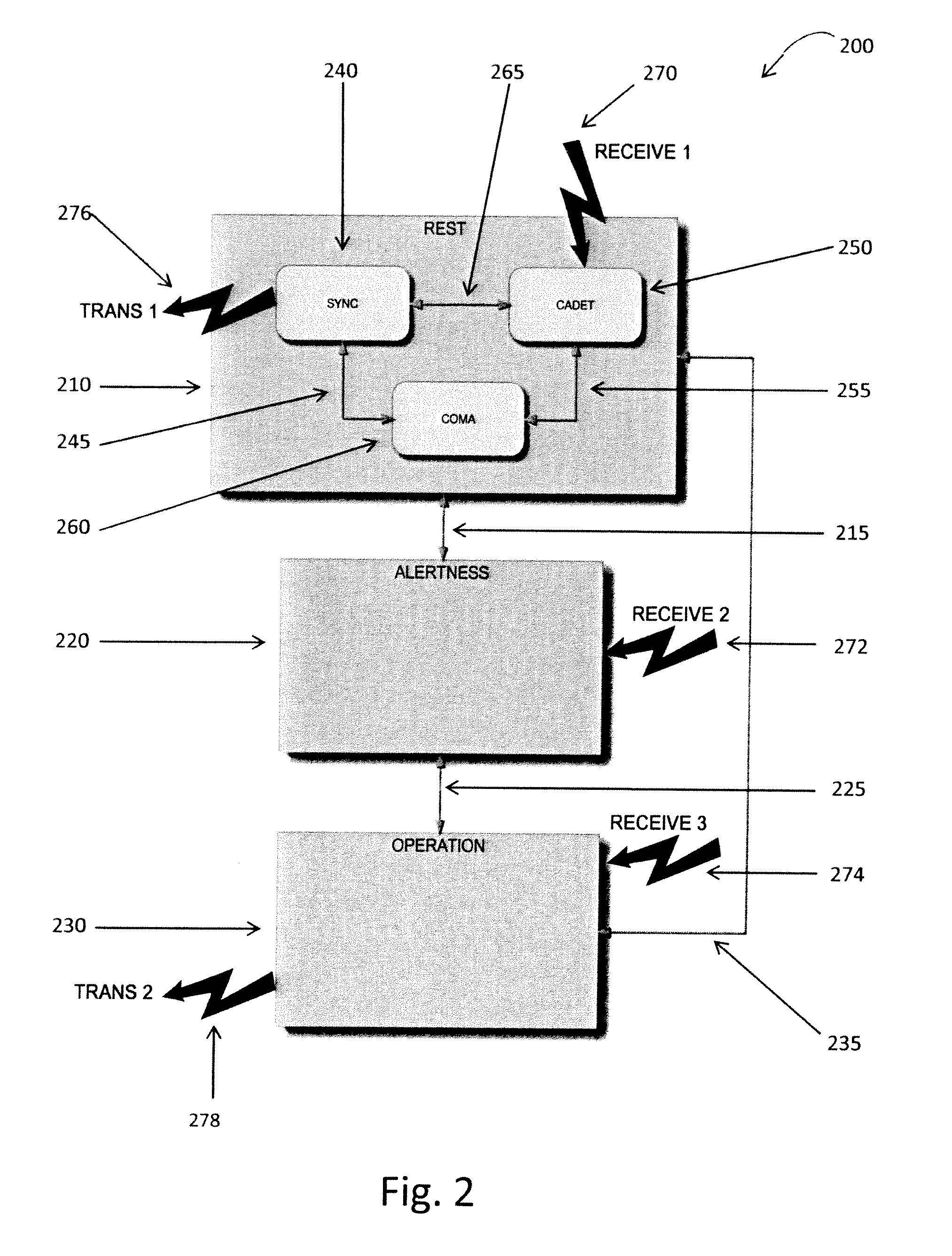
[0014]One embodiment would include at least one mobile handheld approaching unit 120. Another embodiment would contain at least one stationary 110 receiving and / or transmitting system. A further embodiment would have the receiver / transmitter mounted in a vehicle 130. The device would be em...


PUM


Abstract

A system and method of tracking animal livestock using electronic frequency signal transmitters and receivers is herein presented. The system involves electronic tags attached to the bodies of livestock. The tags transmit a signal which conveys the location or other pertinent information regarding the status of the animal. The signals are picked up by a receiver attached to a stationary platform, or located in a vehicle, or in a portable hand held receiver device. The information transmitted can be used to locate a specific animal or can be used to monitor the status and condition of the animal. The device contains several modes which minimize power consumption and maximize power supply lifetime.

Description

[0001]This application claims priority to U.S. Provisional Application Ser. No. 61 / 382,655 filed Sep. 14, 2011. The entirety of this application is hereby incorporated herein by reference in its entirety.BACKGROUND[0002]Anyone who ever saw a cowboy try to catch a cow using a rope knows that fetching an individual farm animal was always one of the toughest jobs on the farm. Approaching an individual farm animal is needed for various reasons; breeding and veterinary treatments are the most common ones. As the number of animals living on a farm increases, more data is collected on individual animals. Needs to approach or fetch specific animals are growing. Therefore, a reliable and cost-efficient solution to the problem of locating a specific animal is needed in the art.[0003]In many prior disclosures, a location of animals is provided by an earth-orbiting satellite system. Such a system requires high power consumption from the device attached to the animal during communication and als...

Claims


Application Information

Patent Timeline
IPC IPC(8): G08B23/00
CPCG01S5/12A01K29/005A01K11/008G01S13/767
Inventor MENACHEM, URI BENBRAYER, EYALLEVI, SHY
Owner SCR ENGINEERS LTD
Learn More