
Magnetic and/or electrostatic Anti-shock device

an anti-shock device and electrostatic technology, applied in the field of anti-shock devices, can solve the problems of reducing the efficiency/quality factor of components during normal operation, and achieve the effect of preserving the integrity of components and their environmen

Active Publication Date: 2012-05-10
MONTRES BREGUET
View PDF4 Cites 24 Cited by
  • Summary
  • Abstract
  • Description
  • Claims
  • Application Information

AI Technical Summary

Benefits of technology

The invention proposes an anti-shock device for protecting timepiece components, particularly those that are pivotally mounted. The device includes a holding means that can move relative to a structure in response to a strong acceleration created by a shock. The holding means can move along an axial direction between stop members. The device also includes means for attracting the component's ends to the holding means, which can move along with the holding means. The invention also concerns a magnetic and / or electrostatic pivot including the anti-shock device. The technical effects of the invention include improved protection against shocks and improved centering of the component.

Problems solved by technology

The problems to be solved are thus as follows:Ensuring precise radial re-centring after the shock.Achieving an anti-shock solution which, is independent of mechanical friction, which has the drawback of reducing the efficiency / quality factor of the components during normal operation, i.e. in the absence of any shocks.
However, the holding of the component on the first pole piece is not equivalent to a support since there is a connection between this component and the internal tubular magnet, via a flange and one of the two sleeves.

Method used


Image

  • Magnetic and/or electrostatic Anti-shock device
  • Magnetic and/or electrostatic Anti-shock device
  • Magnetic and/or electrostatic Anti-shock device

Examples


Embodiment Construction

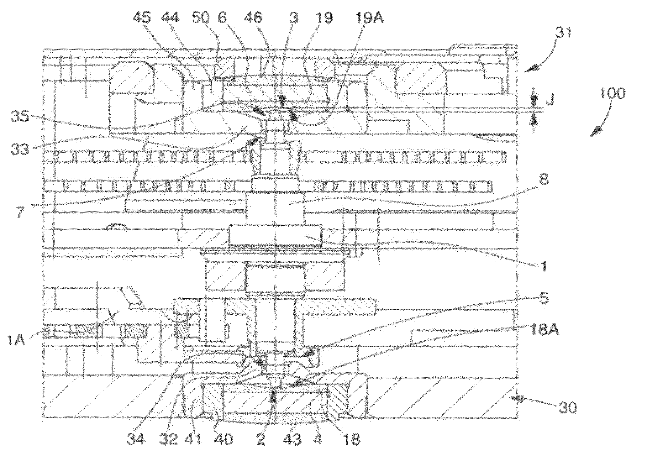
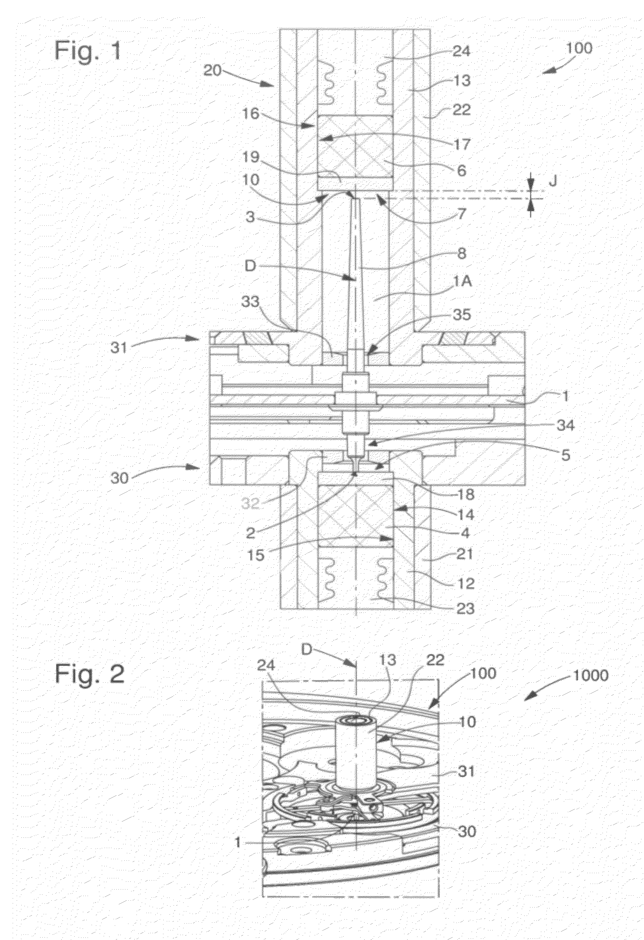
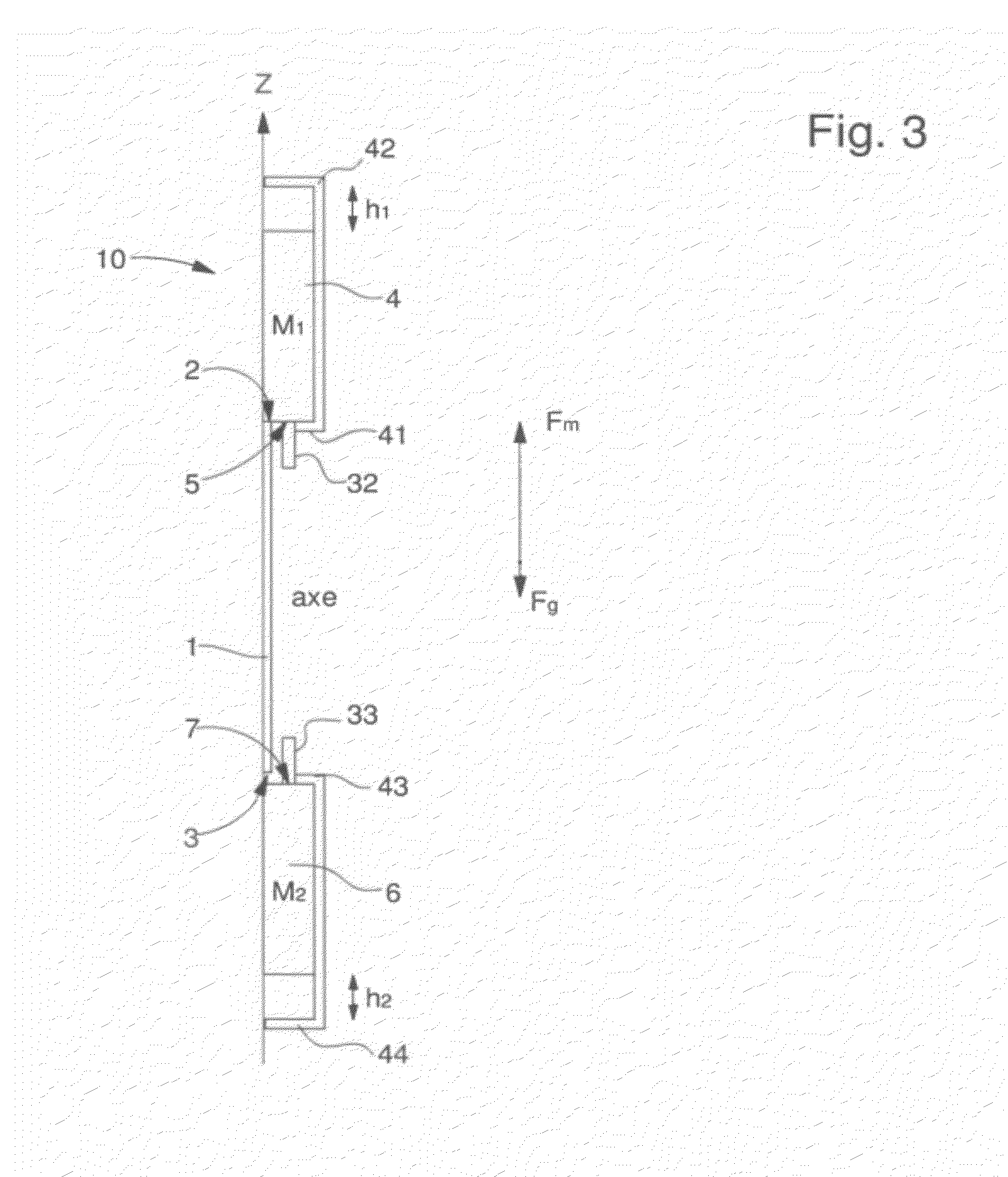
[0030]Thus, the invention concerns an anti-shock device 10 for the protection of a timepiece component 1 pivotally mounted between a first end 2 and a second end 3.

[0031]This anti-shock device 10 includes, on both sides of said first end 2 and second end 3, on the one hand, means for guiding the pivoting of or means for attracting first end 2, held abutting on a first pole piece 4, distinct from component 1 and, on the other hand, in proximity to a second pole piece 6, distinct from component 1, means for guiding the pivoting of the second end 3 or means for attracting said second end 3 to the second pole piece 6.

[0032]Component 1 is, at least in proximity to the first end 2 and the second end 3 thereof, preferably made of a magnetically permeable and / or conductive material. In a particular embodiment of the invention, this material is also magnetised and / or electrized.

[0033]Component 1 can move in a chamber 1A. A “pole piece” means a mass, which, at least in proximity to chamber 1A...


PUM


Abstract

Anti-shock device (10) for the protection of a timepiece component (1) pivotally mounted between a first (2) and a second (3) end in a chamber (1A).Said component (1) is freely mounted in said chamber (1A) between pole pieces (4, 6), which are distinct from said component (1) and located in proximity to said chamber (1A) and the device (10) includes means for attracting said first end (2) held in abutment on only the first pole piece (4), and means for attracting said second end (2) towards a second pole piece (6), said attraction means of said first end (2) and said second end (3), which are of magnetic and / or electrostatic nature, can move along an axial direction (D) between stop members.

Description

[0001]This application claims priority from European Patent Application No. 10190511.1 filed Nov. 9, 2010, the entire disclosure of which is incorporated herein by reference.FIELD OF THE INVENTION[0002]The invention concerns an anti-shock device for the protection of a timepiece component, made of material that is at least partially magnetically permeable or respectively at least partially magnetic, and / or of material that is at least partially conductive or respectively at least partially electrized, wherein said component is pivotally mounted in a chamber between a first end and a second end of said component.[0003]The invention also concerns an anti-shock device of this type for the protection of a timepiece component, made of material that is at least partially magnetically permeable, or at least partially magnetic at a first end and at a second end.[0004]The invention further concerns an anti-shock device of this type for the protection of a timepiece component, made of materia...

Claims


Application Information

Patent Timeline
Patent Type & Authority Applications(United States)
IPC IPC(8): G04B37/04
CPCG04B31/02G04B31/00G04B31/004
Inventor MARECHAL, SYLVAINSARCHI, DAVIDE
Owner MONTRES BREGUET
Learn More