
Image forming apparatus

Active Publication Date: 2012-05-10
KYOCERA DOCUMENT SOLUTIONS INC
View PDF3 Cites 10 Cited by
  • Summary
  • Abstract
  • Description
  • Claims
  • Application Information

AI Technical Summary

Benefits of technology

[0010]In view of the above-described problems, it is an object of the present invention to provide an image forming apparatus that, even in a case of performing fixing processing with respect to a small-sized recording medium, efficiently eliminates a temperature difference between a paper passing region and a non-paper passing region of a fixing device.

Problems solved by technology

This conventional type of fixing device, however, has presented a problem that there occurs a temperature difference on the surface of the pressing roller.
If, in this state, the fixing roller and the pressing roller are started to rotateat the time of image formation, until a predetermined temperature is reached, such a local temperature difference of the pressing roller adversely affects fixing processing, resulting in the occurrence of unevenness in fixing.
This is attributable to the fact that heat is consumed for fixing processing in the paper passing region through which a paper sheet is passed, whereas no heat is consumed in the non-paper passing region, which leads to an increasing temperature difference between the paper passing region and the non-paper passing region.
In the configuration in which the fans are disposed in the conveyor unit, however, the fans, which are provided on an upstream side of the fixing device in a paper conveying direction, end up cooling mainly areas along a paper conveying path corresponding to the non-paper passing regions and, therefore, do not directly cool the fixing roller or the pressing roller, which has been problematic in that cooling efficiency is lowered.
Furthermore, in the configuration in which the duct is provided to cool the roller end portions (non-paper passing regions), hot air generated as a result of cooling the fixing roller might remain in the apparatus main body, which has been problematic in that the fixing roller cannot be cooled efficiently.

Method used


Image

  • Image forming apparatus
  • Image forming apparatus
  • Image forming apparatus

Examples


working examples

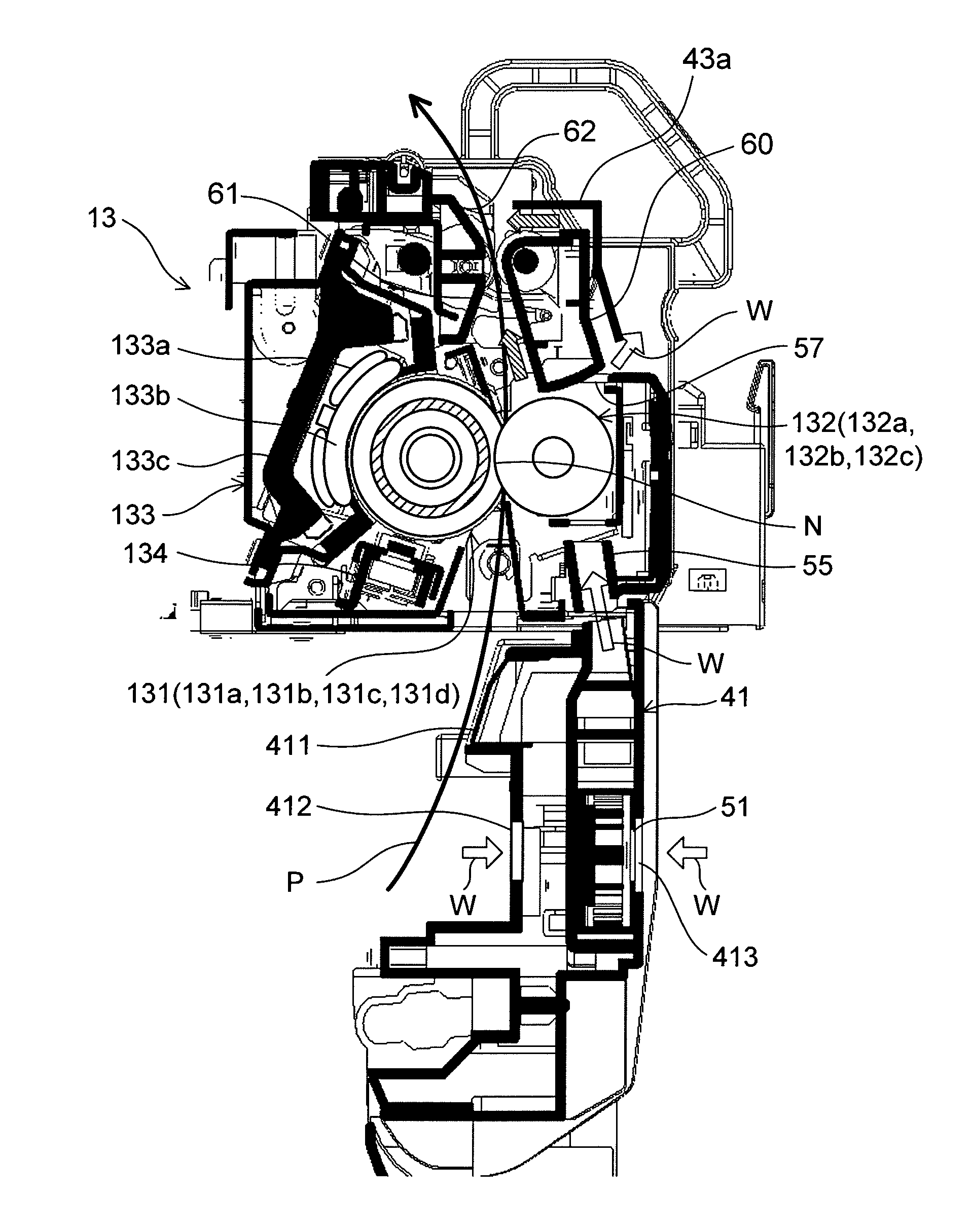
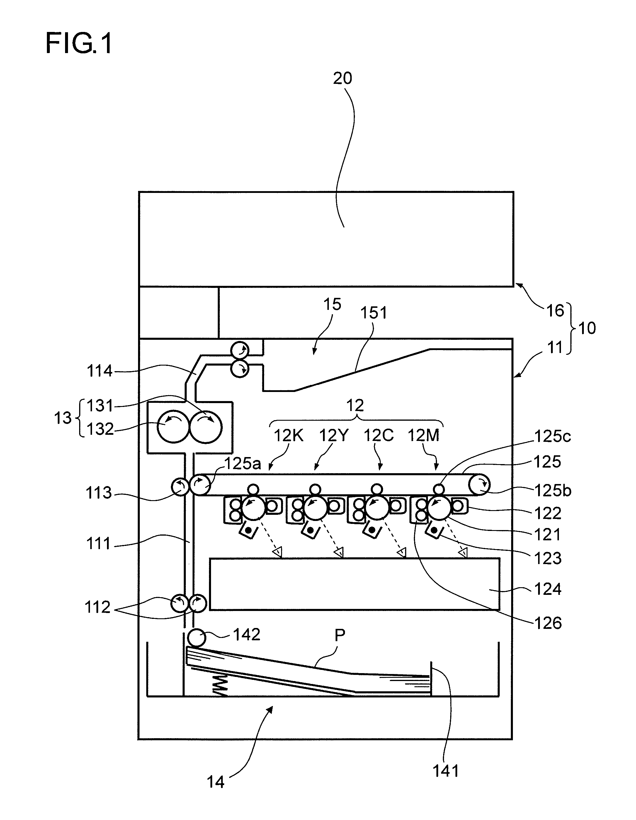
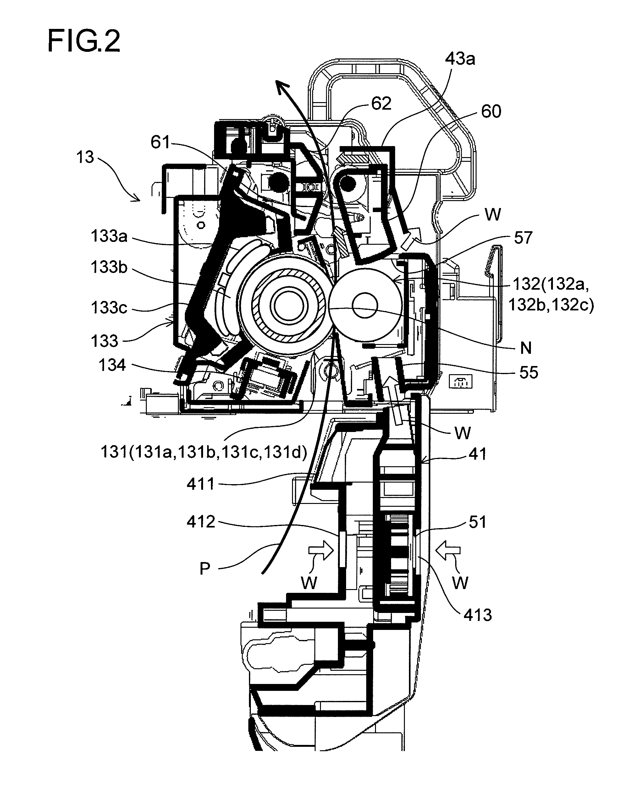
[0079]The dew condensation prevention effect provided by the image forming apparatus of the present invention was evaluated in the following manner. That is, a tandem color copy machine (manufactured by Kyocera Mita Corporation) as shown in FIG. 1 was installed in an environment where dew condensation was likely to be generated (machine's external temperature: 25° C., machine's internal temperature: 10° C., machine's external humidity: 70%). With respect to each of a case where, with no air passing openings provided in the first conveying guide 60 as in the first embodiment, the sirocco fan 51 was started to rotate concurrently with the start of printing (Working Example 1), a case where, with the air passing openings 65a and 65b provided in the first conveying guide 60 as in the second embodiment, the sirocco fan 51 was started to rotate intermittently concurrently with the start of printing so as to have an air volume reduced to half (Working Example 2), and a case where the siroc...


PUM


Abstract

An image forming apparatus includes a fixing device that has: a fixing roller heated by induction and a pressing roller brought into press-contact with the fixing roller to fix a toner image borne on a paper sheet conveyed toward the fixing device by a conveyor unit. When a paper sheet having a width smaller than a width of a maximum-width recording medium that can be passed through the fixing device is passed through the fixing device, a non-paper passing region is formed at each end portion of each of the fixing and pressing rollers. Sirocco fans cool the non-paper passing region at a part of an outer peripheral surface of the pressing roller. The pressing roller is disposed opposed to the outer side of the main body of the image forming apparatus.

Description

BACKGROUND OF THE INVENTION[0001]This application is based on Japanese Patent Application No. 2010-250005 filed on Nov. 8, 2010 and Japanese Patent Application No. 2010-282582 filed on Dec. 20, 2010, the contents of which are hereby incorporated by reference.FIELD OF THE INVENTION[0002]The present invention relates to an image forming apparatus including a fixing device and using an electrophotographic method, such as a copy machine, a printer, a facsimile, or a complex machine having functions of these apparatuses, and particularly relates to an image forming apparatus that performs cooling of a non-paper passing region of a fixing device.DESCRIPTION OF RELATED ART[0003]Conventionally, in a fixing device used in an electrophotographic image forming apparatus, a paper sheet on which a toner image is formed is fed into a nip between a fixing roller that is heated and a pressing roller, where the toner on the paper sheet is melted under a heating action by the fixing roller, and concu...

Claims


Application Information

Patent Timeline
IPC IPC(8): G03G15/20
CPCG03G15/2042G03G2221/1645
Inventor KUROTSU, YOSHIHIKOTAKAHASHI, HIRONORI
Owner KYOCERA DOCUMENT SOLUTIONS INC
Learn More