Ultrasound treatment system and method of actuating the ultrasound treatment system

a treatment system and ultrasound technology, applied in the field of ultrasound treatment system, can solve the problems of deteriorating the observation function of the endoscope observation window, changing the mist color of the fluid,

Inactive Publication Date: 2012-05-10
OLYMPUS MEDICAL SYST CORP
View PDF4 Cites 142 Cited by
  • Summary
  • Abstract
  • Description
  • Claims
  • Application Information

AI Technical Summary

Benefits of technology

[0010]An ultrasound treatment system according to an aspect of the present invention includes: an ultrasound driving signal generating section that generates an ultrasound driving signal; an ultrasound treatment section that treats a treatment target living tissue with ultrasound vibration by being applied with the ultrasound driving signal; an observing section that has an observation function for observing the treatment target living tissue; an image acquiring section that acquires, via the observing section, as an observed image, an image of the living tissue that changes according to an amount of mist that occurs during a treatment of the living tissue; a storing section that stores an image of the living tissue in a state in which the mist does not occur in the storing section in advance as a reference image; a comparing section that compares the observed image acquired by the image acquiring section and the reference image stored in the storing section; a determining section that determines, on the basis of a comparison result of the comparing section, whether the observed image is an image that has changed a predetermined value or more with respect to the reference image; and a control section that performs control for stopping or reducing output of the ultrasound driving signal when it is det

Problems solved by technology

Therefore, when the ultrasound vibration energy is given to the treatment target living tissue, since the ultrasound vibration energy is given to

Method used


Image

  • Ultrasound treatment system and method of actuating the ultrasound treatment system
  • Ultrasound treatment system and method of actuating the ultrasound treatment system
  • Ultrasound treatment system and method of actuating the ultrasound treatment system

Examples


first embodiment

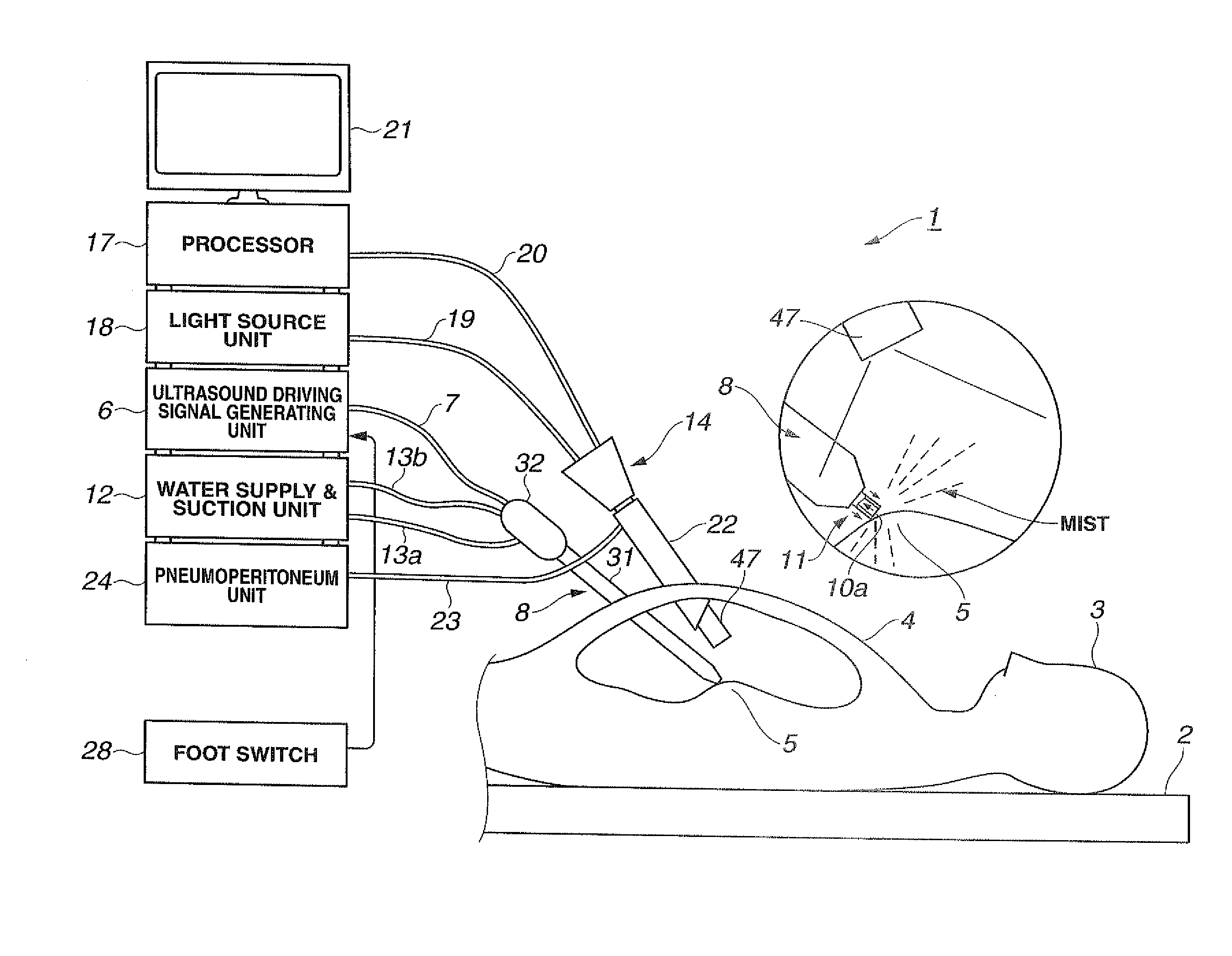
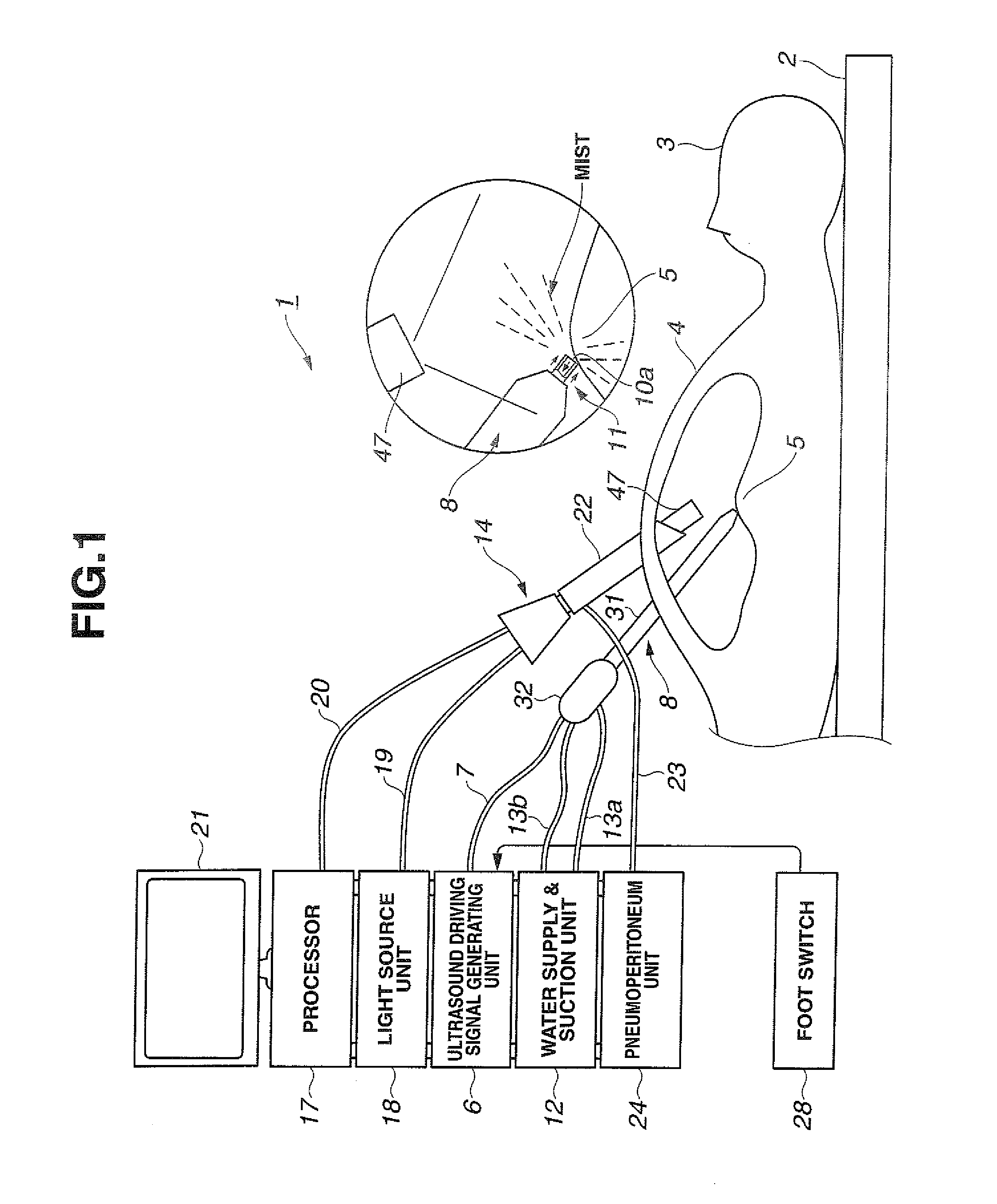
[0042]As shown in FIG. 1, an ultrasound suction system 1 according to a first embodiment of the present invention applies, using ultrasound vibration energy (abbreviated as ultrasound vibration), treatment to, for example, a living tissue of a diseased part 5 set as a treatment target in an abdomen 4 of a patient 3 lying on a bed 2.

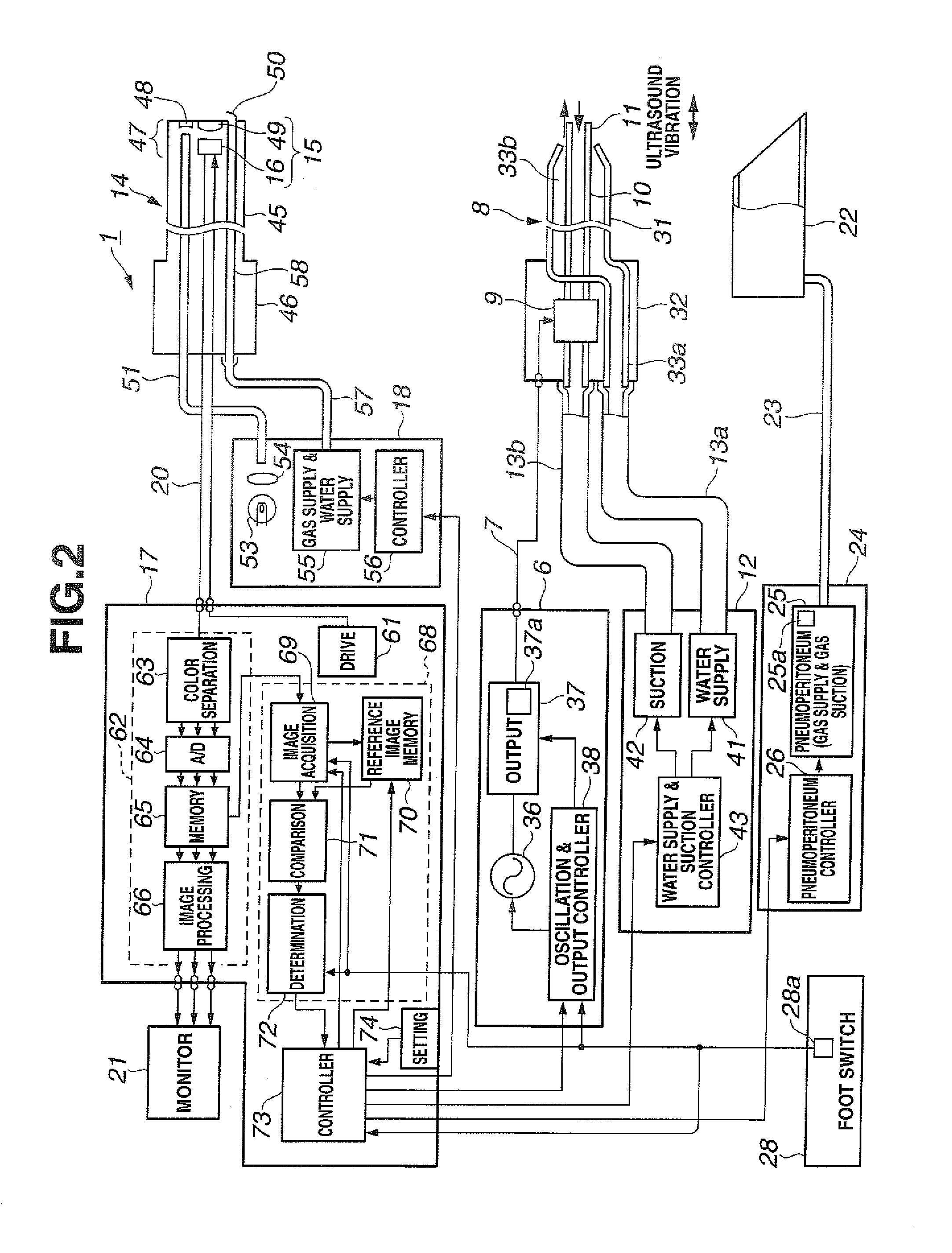
[0043]Therefore, the ultrasound suction system 1 includes an ultrasound driving signal generating unit 6 that generates an ultrasound driving signal for generating ultrasound vibration. The ultrasound driving signal generating unit 6 outputs the generated ultrasound driving signal to an ultrasound suction probe 8 functioning as an ultrasound suction section via a signal cable 7.

[0044]As shown in FIG. 2, the ultrasound suction probe 8 incorporates an ultrasound transducer 9 functioning as an ultrasound generating section that generates ultrasound vibration by being applied with the ultrasound driving signal from the ultrasound driving signal generating uni...

second embodiment

[0198]FIG. 14A shows a configuration of an ultrasound suction probe 8B according to a second embodiment of the present invention. This embodiment includes means for preventing, even when mist scatters, the scatter from affecting a satisfactory observation field of view of the endoscope 14. Other components are the same as, for example, those in the first embodiment.

[0199]In the ultrasound suction probe 8B, the outer pipe 31 of the ultrasound suction probe 8B shown in FIG. 2 is replaced with an inner sheath 91a and an outer sheath 91b is provided on an outer side of the inner sheath 91a.

[0200]A distal end of the outer sheath 91b is located further on a rear side than a distal end of the inner sheath 91a. The distal end portion 11 of the ultrasound suction probe 8B arranged on an inner side of the inner sheath 91a is arranged to slightly project from a distal end portion of the inner sheath 91a.

[0201]In a distal end side portion between the inner sheath 91a and the outer sheath 91b,...

third embodiment

[0209]FIGS. 16A and 16B show a configuration on a distal end side of an ultrasound suction probe 8C according to a third embodiment of the present invention.

[0210]In this embodiment, for example, in the ultrasound suction probe 8 shown in FIGS. 1 and 2 in the first embodiment, the ultrasound suction probe 8C is formed by detachably attaching a bag 95a, which is formed of, for example, a transparent member, on the distal end side of the ultrasound suction probe 8.

[0211]The bag 95a is formed in a substantially semispherical shape or a conical shape. A proximal end of the bag 95a is detachably attached to the outer pipe 31 of the ultrasound suction probe 8 by a ring 95b having elasticity such as rubber. A distal end side of the bag 95a is opened in a substantially circular shape.

[0212]FIG. 17 shows a state in which processing utilizing ultrasound vibration is performed using the ultrasound suction probe 8C in this embodiment.

[0213]In this embodiment, a peripheral portion of the treatme...


PUM


Abstract

An ultrasound treatment system applies an ultrasound driving signal generated by an ultrasound driving signal generating section on an ultrasound treatment section, treats a treatment target living tissue with ultrasound vibration under observation by an observing section, and acquires, with an image acquiring section, an observed image of the living tissue being treated. A control section controls, for example, output of the ultrasound driving signal on the basis of a comparison result of the observed image and a reference image of the living tissue in a state in which mist does not occur.

Description

CROSS REFERENCE TO RELATED APPLICATION[0001]This application is a continuation application of PCT / JP2011 / 063511 filed on Jun. 13, 2011 and claims benefit of U.S. Provisional Patent Application No. 61 / 355,646 filed in the U.S.A. on Jun. 17, 2010, the entire contents of which are incorporated herein by this reference.BACKGROUND OF THE INVENTION[0002]1. Field of the Invention[0003]The present invention relates to an ultrasound treatment system that performs suction using ultrasound and a method of actuating the ultrasound treatment system.[0004]2. Description of the Related Art[0005]In recent years, various kinds of treatments for medical treatment for patients are widely performed under endoscope observation employing an endoscope.[0006]In order to make it easy to perform treatment, in some cases, an ultrasound suction apparatus or an ultrasound suction system is used that gives ultrasound vibration energy to a treatment target living tissue, fragments a fragile tissue with ultrasound...

Claims


Application Information

Patent Timeline
IPC IPC(8): A61N7/00A61B8/00
CPCA61B17/320068A61B19/52A61B19/5212A61B2017/00022A61B2218/007A61B2017/00137A61B2017/00902A61B2019/5289A61B2218/002A61B2017/00057A61B90/36A61B2090/364A61B90/361A61B2017/32007A61B2017/320069
Inventor SAWADA, YUKIHIKOYAMADA, NORIHIROTSUKIYAMA, SHUSAKU
Owner OLYMPUS MEDICAL SYST CORP
Why Eureka
Try Eureka