Apparatus and method for igniting a combustor

Active Publication Date: 2012-05-17
GENERAL ELECTRIC CO
View PDF5 Cites 25 Cited by
  • Summary
  • Abstract
  • Description
  • Claims
  • Application Information

AI Technical Summary

Problems solved by technology

However, the size and number of nozzles 18 located in the breech end of the co

Method used


Image

  • Apparatus and method for igniting a combustor
  • Apparatus and method for igniting a combustor
  • Apparatus and method for igniting a combustor

Examples


Embodiment Construction

[0018]Reference will now be made in detail to present embodiments of the invention, one or more examples of which are illustrated in the accompanying drawings. The detailed description uses numerical and letter designations to refer to features in the drawings. Like or similar designations in the drawings and description have been used to refer to like or similar parts of the invention.

[0019]Each example is provided by way of explanation of the invention, not limitation of the invention. In fact, it will be apparent to those skilled in the art that modifications and variations can be made in the present invention without departing from the scope or spirit thereof. For instance, features illustrated or described as part of one embodiment may be used on another embodiment to yield a still further embodiment. Thus, it is intended that the present invention covers such modifications and variations as come within the scope of the appended claims and their equivalents.

[0020]Various embodi...


PUM


Abstract

A nozzle includes a center body that defines an axial centerline. A shroud circumferentially surrounds at least a portion of the center body to define an annular passage between the center body and the shroud. A plenum is inside the center body and substantially parallel to the axial centerline, and an igniter is inside the center body and generally adjacent to the plenum. A method for igniting a combustor includes flowing a fuel through a center body axially aligned in a nozzle and flowing a working fluid through an annular passage, wherein the annular passage is substantially parallel to and radially outward of the center body. The method further includes projecting at least one of a beam, spark, or flame from an igniter located inside the center body.

Description

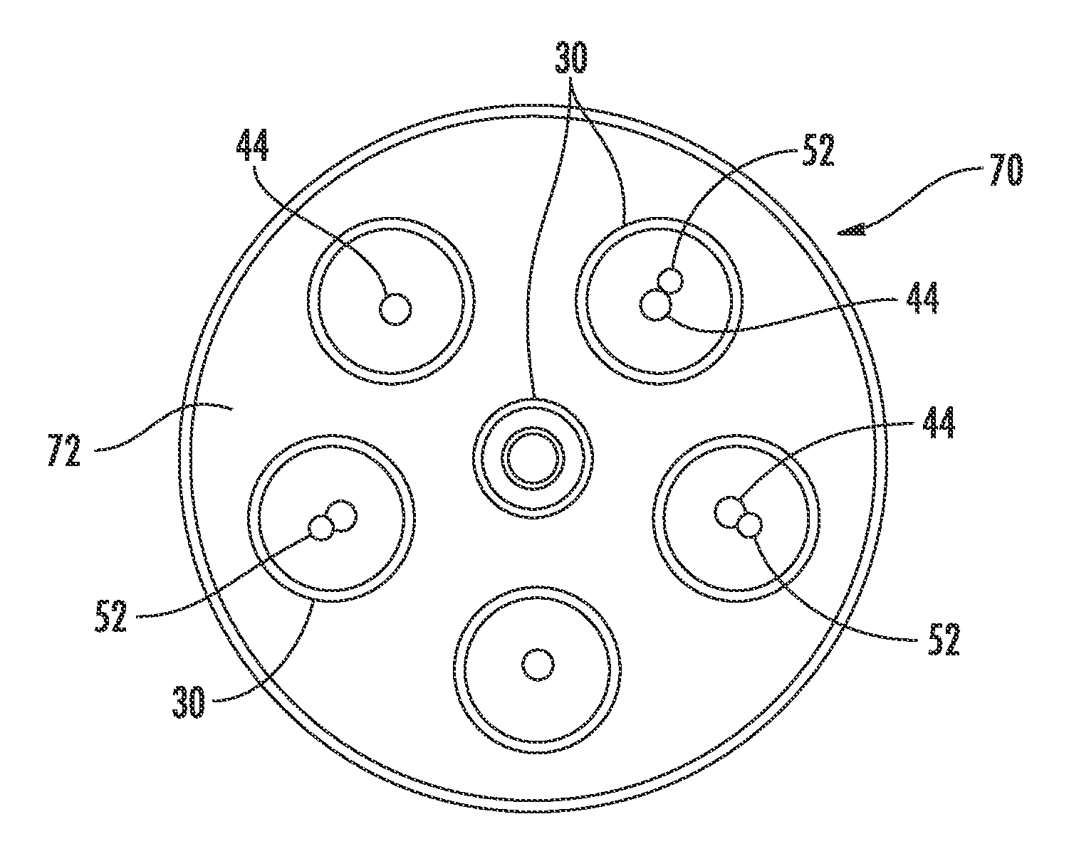
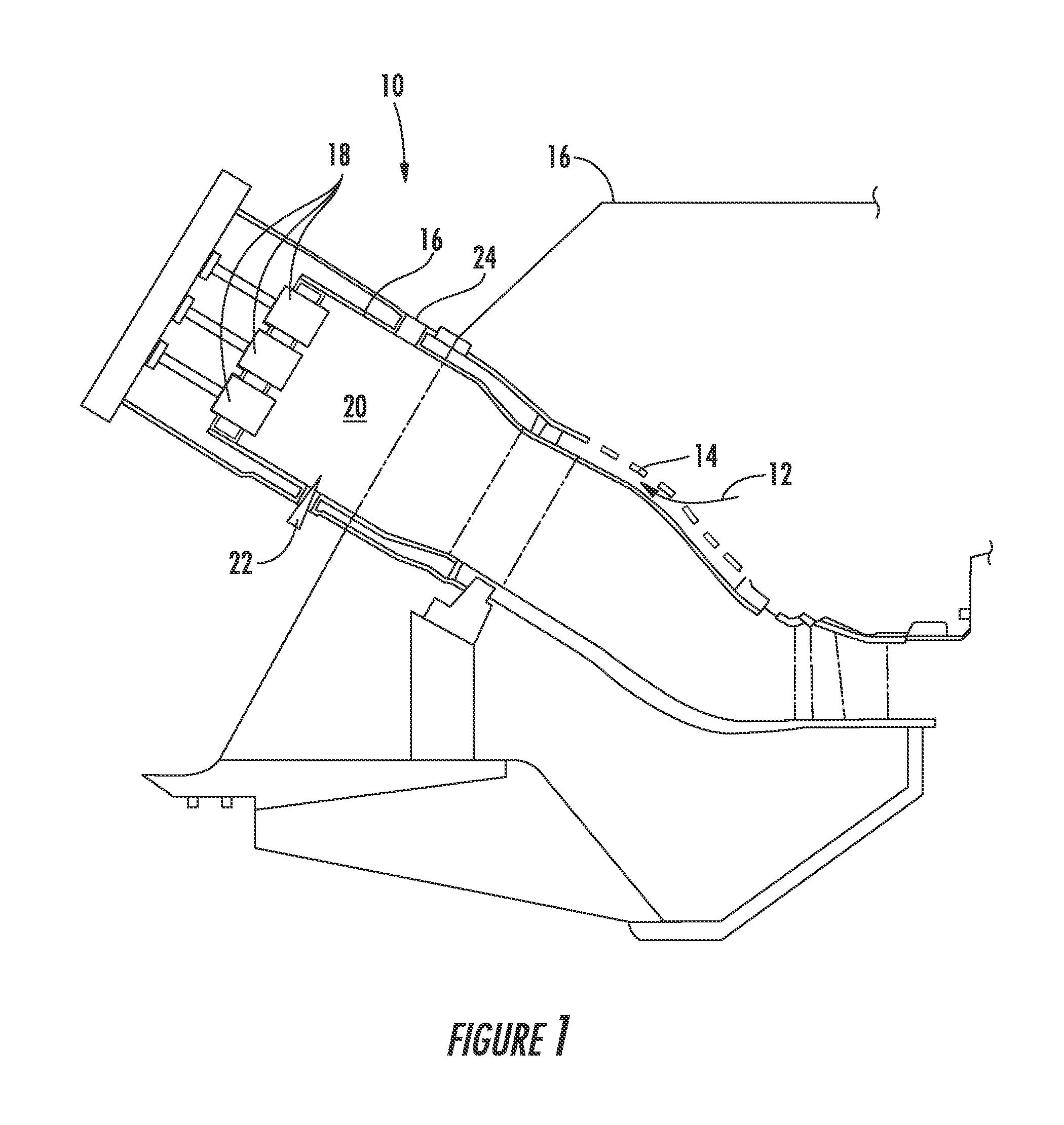
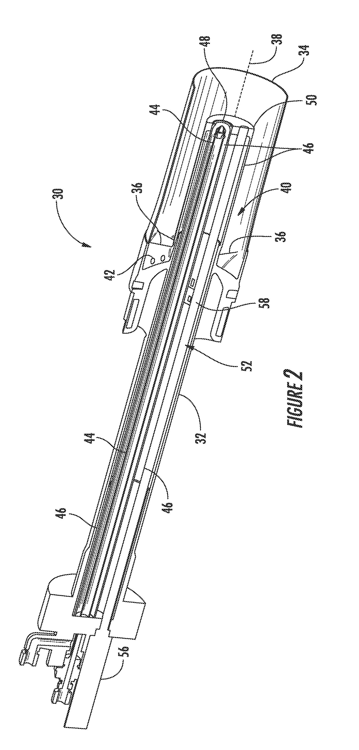
FIELD OF THE INVENTION[0001]The present invention generally involves an apparatus and method for igniting a combustor. In particular embodiments, the apparatus may comprise a nozzle or a combustor having an igniter aligned with an axial centerline of the nozzle.BACKGROUND OF THE INVENTION[0002]Gas turbines, aircraft engines, and numerous other combustion-based systems include one or more combustors that mix a working fluid such as air with fuel and ignite the fuel-air mixture to produce high temperature and pressure combustion gases. FIG. 1 shows a simplified cross-section of a combustor 10 that might be included, for example, in a gas turbine. A working fluid 12 may flow between a flow sleeve 14 and a liner 16 before reversing direction and flowing through one or more nozzles 18 into a combustion chamber 20. The nozzles 18 mix the fuel with the working fluid 12, and an ignition system 22 ignites the fuel-air mixture in the combustion chamber 20.[0003]The ignition system 22 may comp...

Claims


Application Information

Patent Timeline
IPC IPC(8): F02C7/264F02C7/22
CPCF02C7/264F02P13/00F23D2207/00F23Q3/008F23R3/286F02P23/04F23R2900/00006
Inventor KRULL, ANTHONY WAYNEMYERS, GEOFFREY DAVIDWESTMORELAND, III, JAMES HAROLD
Owner GENERAL ELECTRIC CO
Why Eureka
Try Eureka