
Method for the precise measuring operation of a micromechanical rotation rate sensor

a technology of rotation rate sensor and precise measurement, which is applied in the direction of acceleration measurement using interia force, turn-sensitive devices, instruments, etc., can solve the problems of undesirable influence, undesired flank angle of respective structures,

Active Publication Date: 2012-05-17
CONTINENTAL TEVES AG & CO OHG +1
View PDF3 Cites 3 Cited by
  • Summary
  • Abstract
  • Description
  • Claims
  • Application Information

AI Technical Summary

Benefits of technology

[0007]An aspect of the present invention is a method in which an undesired influence on the frequency / resonant frequency of the readout mode of the rotation rate sensor in the course of quadrature suppression can be avoided and, in particular, a desired resonant frequency can be set in conjunction with quadrature suppression.
[0024]The rotation rate sensor is preferably produced by means of at least one micromechanical method. In this case, the structures are etched into a diaphragm material, in particular silicon, particularly preferably using anisotropic dry etching substantially perpendicularly through the diaphragm. The plane of the diaphragm base area extends substantially parallel to the substrate surface. At the locations where the diaphragm is permanently connected to the substrate lying therebelow, anchoring points are produced at which, in turn either spring elements or fixed structures are fastened. As a result, rigid bodies that are suspended from springs can be implemented in a freely vibrating fashion. The anchoring points are very particularly preferably electrically insulated from one another by insulating layers, and contact can be made with them from outside.

Problems solved by technology

It is known that micromechanical springs for suspending seismic masses in rotation rate sensors in part cause deflections in the readout direction in the drive mode simply because of relatively slight manufacturing inaccuracies, which in the absence of a rotation rate lead, in particular, to undesired flank angles of the respective structures.
As a result of this, interference signals are generated that can undesirably be evaluated as rotation rate signal components, and thus corrupt the rotation rate signal and / or cause a measuring error with reference to the rotation rate signal.
However, this quadrature suppression can have an undesirable influence on the resonant frequency of the readout mode of the rotation rate sensor, as a result of which the difference frequency between the resonant frequencies with regard to the drive mode and the readout mode of the rotation rate sensor is also changed.
This is all the more disadvantageous because the voltage applied to the trimming electrodes is squared in the shift of the resonant frequency of the readout mode.

Method used


Image

  • Method for the precise measuring operation of a micromechanical rotation rate sensor
  • Method for the precise measuring operation of a micromechanical rotation rate sensor
  • Method for the precise measuring operation of a micromechanical rotation rate sensor

Examples


Embodiment Construction

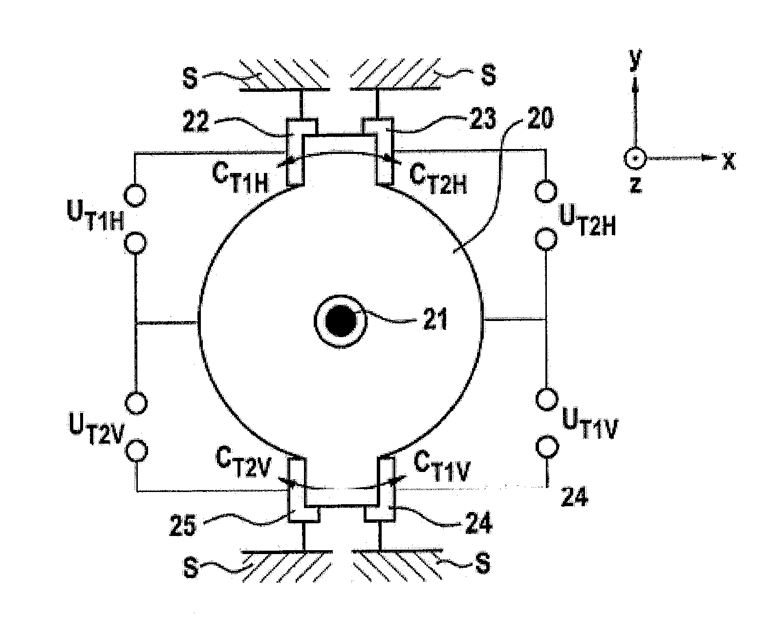
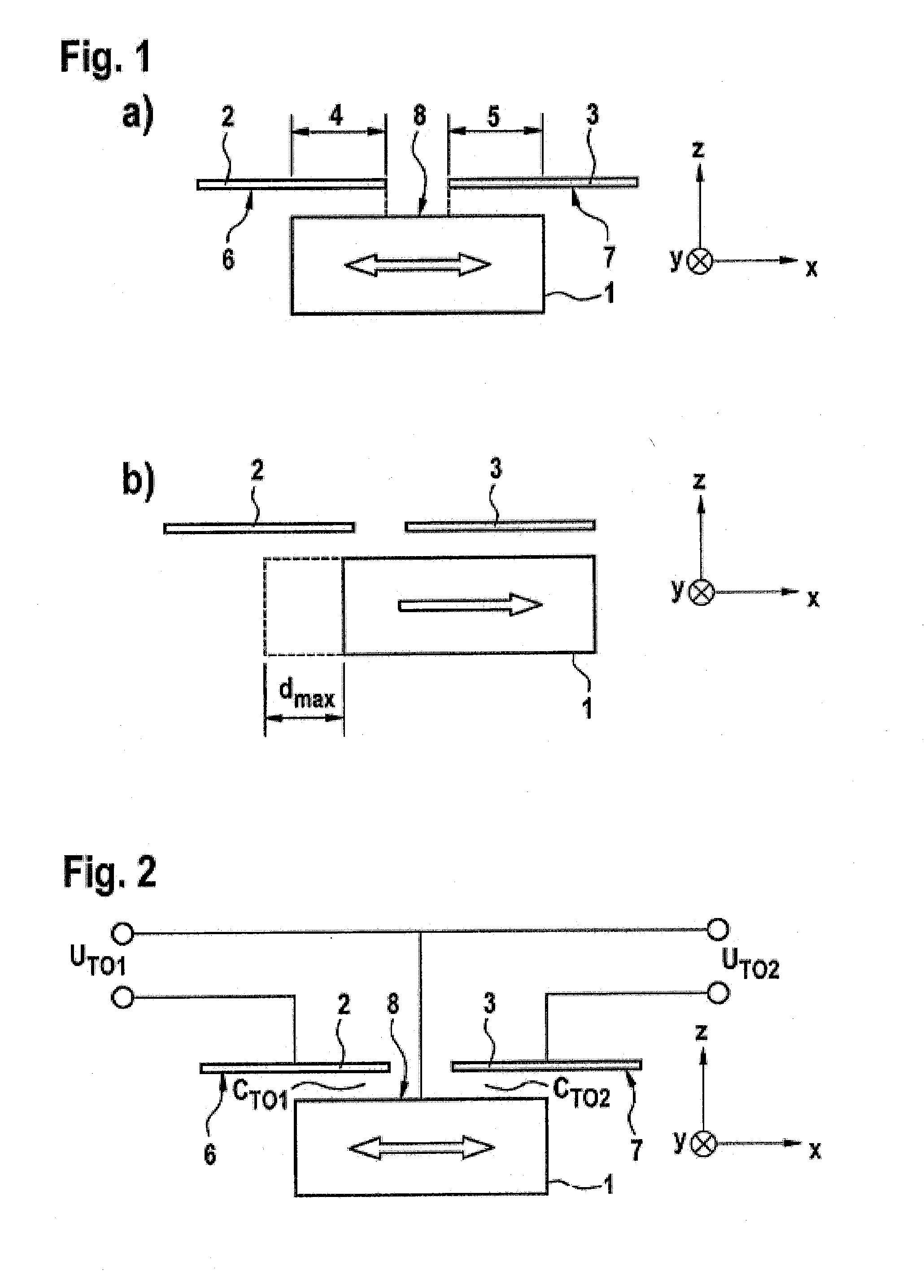
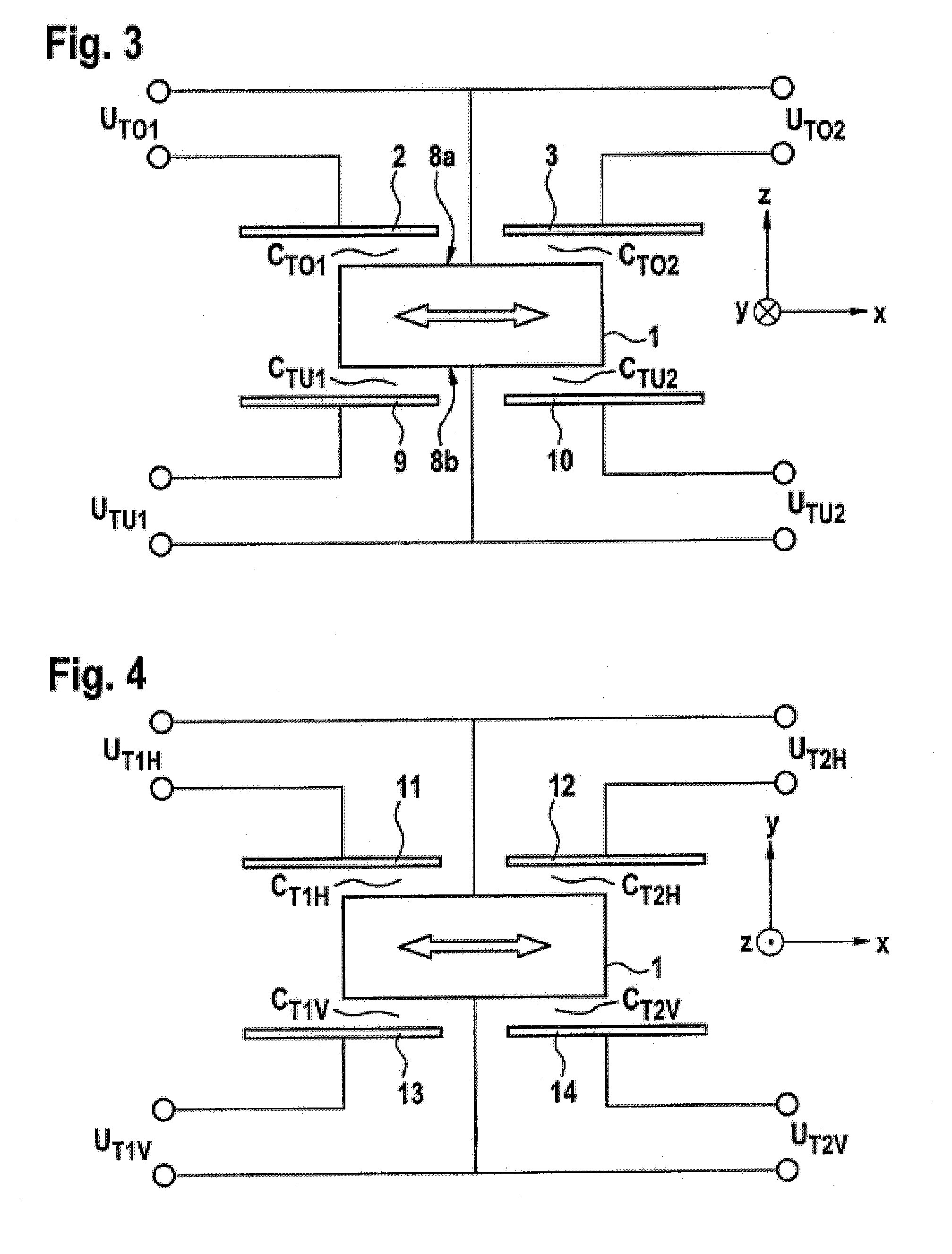
[0056]Exemplary embodiments in FIGS. 1 to 10 of at least partially illustrated micromechanical rotation rate sensors are respectively aligned in relation to a Cartesian x-y-z coordinate system of an inertial system whose rotation rate is to be acquired. With reference to this coordinate system, the drive direction for the at least one seismic mass in the x-direction and the respectively exemplary rotation rate sensor, are designed such that the sensor can acquire rotation rates at least around the z-axis and / or y-axis. Moreover, these rotation rate sensors have an application direction or structuring direction in the z-direction with reference to which said sensors are formed from a silicon wafer. In the case of these exemplary embodiments, the trimming electrode elements are respectively arranged immovably, and formed and arranged in a fashion electrically insulated from one another and from the seismic mass. The trimming electrode elements are respectively designed by way of examp...


PUM


Abstract

A method and apparatus for the precise measuring operation of a micromechanical rotation rate sensor, including at least one deflectively suspended seismic mass, at least one drive device for driving the seismic mass, and at least one first and one second trimming electrode element, which are jointly assigned directly or indirectly to the seismic mass, a first electrical trimming voltage (UTO1, UTLO1, UTRO1) being set between the first trimming electrode element and the seismic mass, and a second electrical trimming voltage (UTO2, UTLO2, UTRO2) being set between the second trimming electrode element and the seismic mass, the first and the second electrical trimming voltages being set at least as a function of a quadrature parameter (UT) and a resonance parameter (Uf).

Description

CROSS REFERENCE TO RELATED APPLICATIONS[0001]This application is the U.S. National Phase Application of PCT / EP2010 / 055708, filed Apr. 28, 2010, which claims priority to German Patent Application No. DE 10 2009 019 318.9, filed Apr. 30, 2009, the contents of such applications being incorporated by reference herein.FIELD OF THE INVENTION[0002]The invention relates to a method for the precise measuring operation of a micromechanical rotation rate sensor in accordance with a method for the precise measuring operation of a micromechanical rotation rate sensor, comprising at least one deflectively suspended seismic mass, at least one drive device for driving the seismic mass and at least one first and one second trimming electrode element, which are jointly assigned directly or indirectly to the seismic mass, a first electrical trimming voltage (UTO1, UTLO1, UTRO1, UTU2, UT1H, UT2V) being set between the first trimming electrode element and the seismic mass, and a second electrical trimmi...

Claims


Application Information

Patent Timeline
IPC IPC(8): G01C19/56
CPCG01C19/5755G01C19/5712
Inventor GUNTHNER, STEFANHILSER, ROLANDSIVARAMAN, RAMNATHSCHMID, BERNHARDKLEMETTI, PETRI
Owner CONTINENTAL TEVES AG & CO OHG
Learn More