Flattened heat pipe and manufacturing method thereof

a heat pipe and flat technology, applied in the field of heat pipes, can solve the problems of large heat dissipation, achieve the effects of enhancing heat transport ability, reducing heat density, and reducing heat loss

Active Publication Date: 2012-05-17
FURUKAWA ELECTRIC CO LTD
View PDF8 Cites 31 Cited by
  • Summary
  • Abstract
  • Description
  • Claims
  • Application Information

AI Technical Summary

Benefits of technology

[0036]According to one aspect of the invention, the wicks formed of the sintered metals thermally contact with the whole flat portion of the inner wall of the flattened container that is in contact with the heat source, so that heat density becomes small and heat can be moved efficiently.
[0037]Still more, because the refluxing portions containing the acute-angled portions are formed among the sintered metals or between the sintered metals and the inner wall of the container and because the capillary force strongly acts especially in the refluxing portions formed by the acute-angled portions, among the curved portions of the sinte

Problems solved by technology

Because the MPUs are extremely integrated and carry out calculations, c

Method used


Image

  • Flattened heat pipe and manufacturing method thereof
  • Flattened heat pipe and manufacturing method thereof
  • Flattened heat pipe and manufacturing method thereof

Examples


Embodiment Construction

[0060]A flattened heat pipe of the invention will be explained in detail below with reference to the drawings.

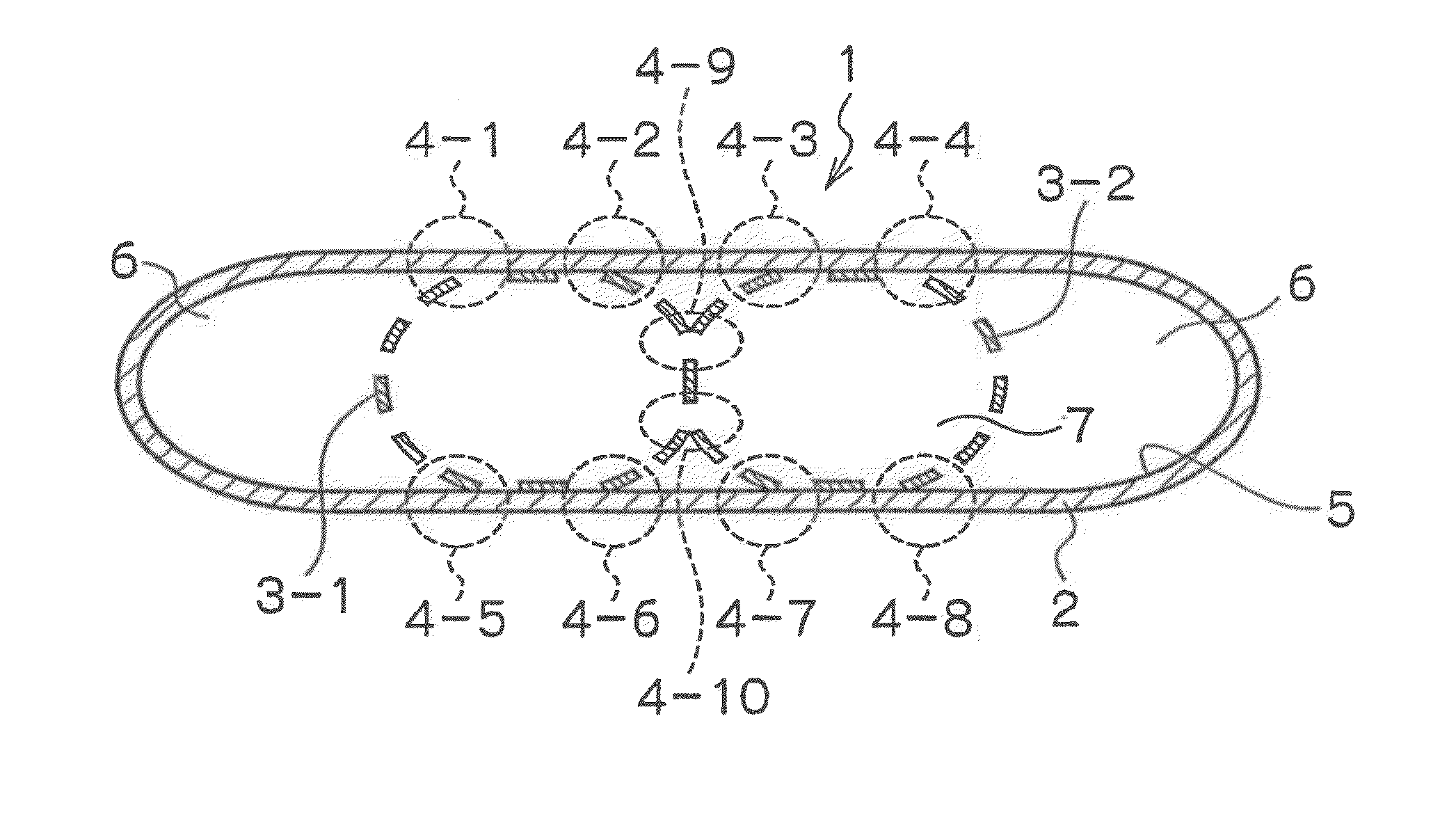
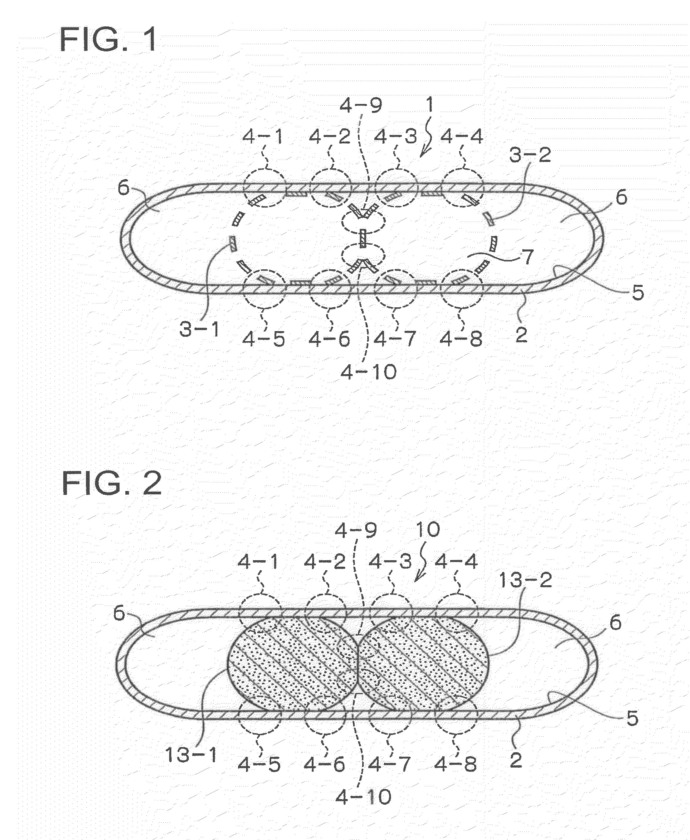
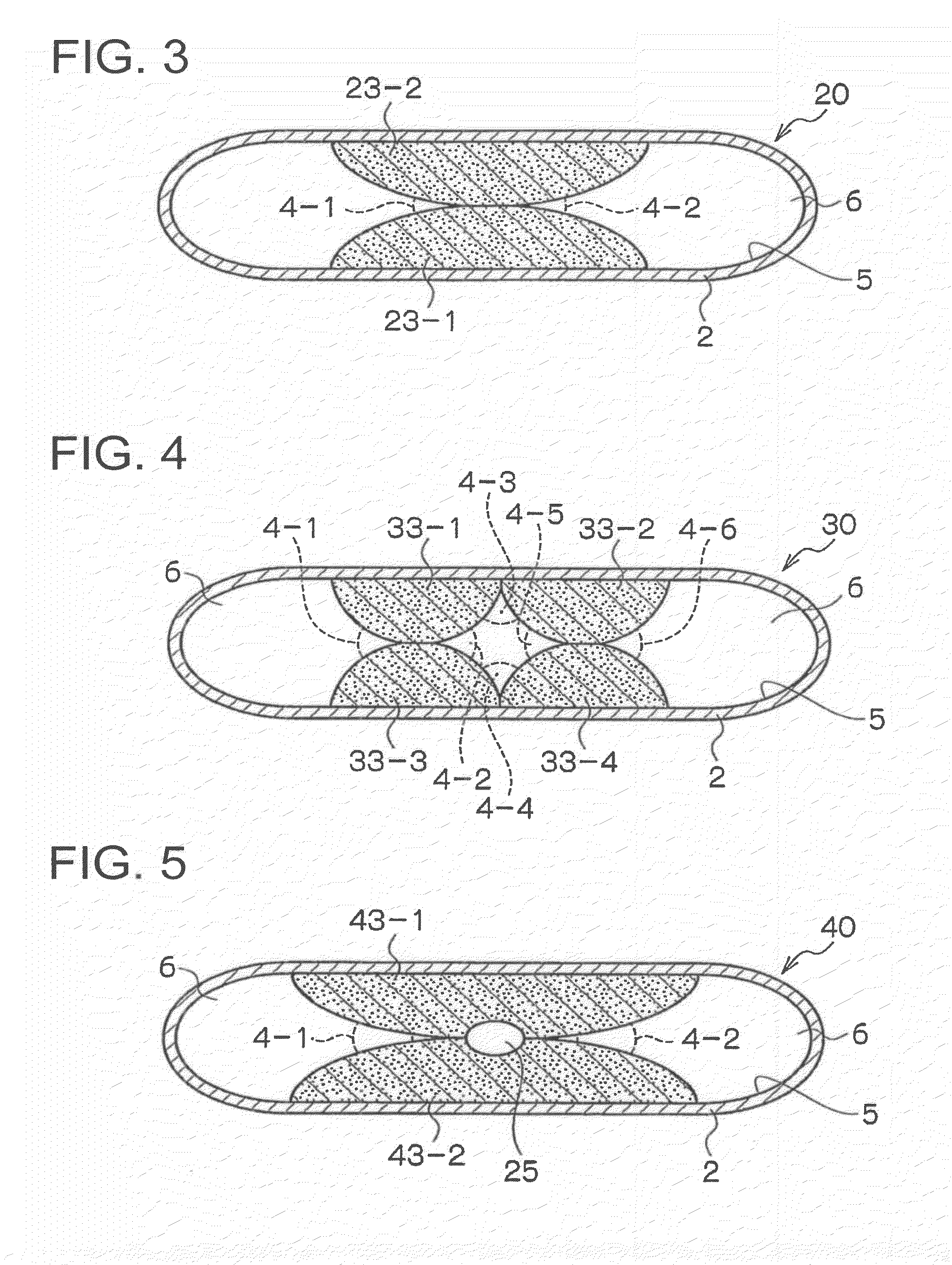
[0061]According to one mode of the invention, the flattened heat pipe has a closed container formed by flattening a tubular container, a plurality of wick structures arrayed in contact with each other in a vertical or horizontal direction in a flat cross-section of the container, a working fluid sealed into the container and a hollow portion through which the gas-phase working fluid passes through, wherein parts where the wick structures are in contact with each other form acute-angled portions.

[0062]In the heat pipe, the wick structures are formed of a plurality of tubular meshes, upper and lower ends of the tubular meshes contact respectively with upper and lower inner walls of the container, a side surface of the tubular mesh contacts with a side surface of the neighboring tubular mesh and the acute-angled portion is formed of at least one of the part where the upper end ...


PUM

PropertyMeasurementUnit
Fractionaaaaaaaaaa
Distanceaaaaaaaaaa
Temperatureaaaaaaaaaa

Abstract

The invention provides a flattened heat pipe whose vapor flowing passage is not clogged and which has an excellent capillary force. The flattened heat pipe has a closed container formed by flattening a tubular container, a plurality of wick structures arrayed within the container in a longitudinal direction so as to form an acute-angled portion where a capillary force is large at least partially within the container, a hollow portion formed of an outer peripheral surface of the wick structure and an inner wall surface of the container and a working fluid sealed into the container.

Description

TECHNICAL FIELD[0001]The present invention relates to a heat pipe for cooling exothermic elements, heat conducting units and others for example of units to be cooled such as a CPU stored in personal computers, electronic devices and others and more specifically to a flattened heat pipe having a large heat transporting quantity.BACKGROUND ART[0002]Lately, with remarkable downsizing and increase of performances of electrical devices such as personal computers, it is being strongly demanded to downsize and to save a space of a cooling mechanism for cooling exothermic parts such as MPUs mounted in the electrical devices. Because the MPUs are extremely integrated and carry out calculations, controls and others in high speed, they dissipate a large amount of heat. Then, various cooling systems have been proposed to cool chips and others, i.e., high-speed, high-output and highly integrated parts. Typical one of such cooling systems is a heat pipe.[0003]Because apparent thermal conductivity...

Claims


Application Information

Patent Timeline
IPC IPC(8): F28D15/04B21D53/02
CPCF28D15/0233F28D15/046H01L23/427Y10T29/49353H01L2924/0002H01L2924/00F28D15/04
Inventor KAMEOKA, HIDEAKISUGIMURA, MASANOBUMIURA, TATSUROSASAKI, YASUMIOKADA, HIROSHIFURUMOTO, SHINICHIYAMAMOTO, MASAAKI
Owner FURUKAWA ELECTRIC CO LTD
Why Eureka
Try Eureka