Insulation resistance measurement device and insulation resistance measurement method

US20120119755A1Inactive Publication Date: 2012-05-17YOSHIDOMI ELECTRIC +3

Image

  • Insulation resistance measurement device and insulation resistance measurement method
  • Insulation resistance measurement device and insulation resistance measurement method
  • Insulation resistance measurement device and insulation resistance measurement method

Examples


Embodiment Construction

[0017]The preferred embodiments of the insulation resistance measurement device and insulation resistance measurement method according to the present invention will be described below in detail with reference to the drawings. In the description of the drawings identical or equivalent portions will be denoted by the same reference signs, without redundant description.

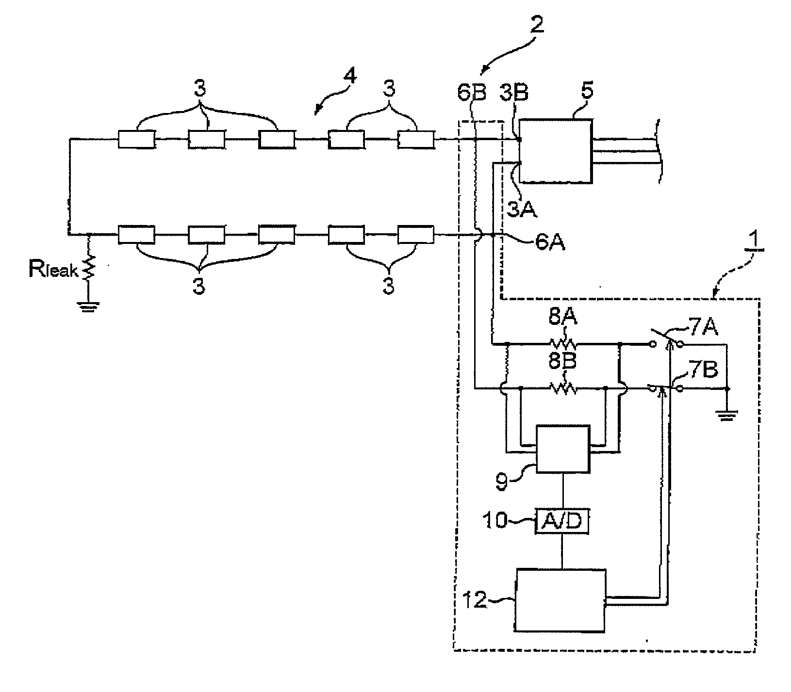
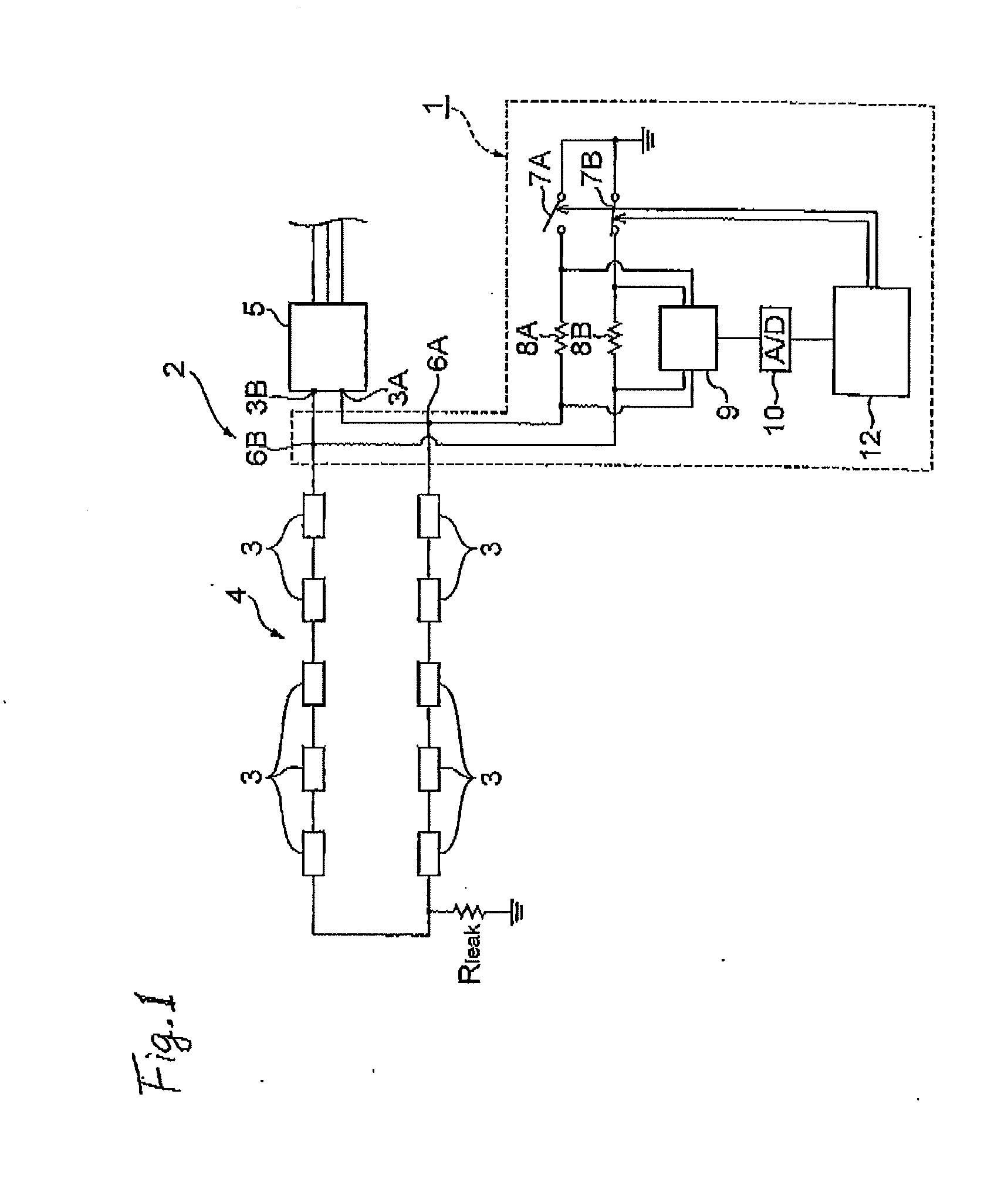
[0018]FIG. 1 is a circuit block diagram showing the configuration of the insulation resistance measurement device 1 according to a preferred embodiment of the present invention, along with a DC source circuit 2 which is an object to be measured. As shown in the same drawing, the insulation resistance measurement device 1 is a device for measuring the insulation resistance to ground, for the object of the DC source circuit 2 including a series power supply 4 in which a plurality of solar cell modules 3 are connected in series, and an inverter circuit 5 connected to a positive electrode 3A and a negative electrode 3B of th...


PUM


Abstract

An object is to detect an insulation failure of a DC circuit with high sensitivity and in safety by means of a simple detection circuit. An insulation resistance measurement device of this invention is a device for measuring an insulation resistance to ground of a DC source circuit and is provided with connection terminals for connections to a positive electrode and a negative electrode of a series power supply, switch elements connected between the connection terminals and the ground potential and configured to switch connections between the connection terminals and the ground potential, resistive elements connected through the switch elements between the connection terminals, respectively, and the ground potential, and a voltage detection unit for detecting voltage drops in the resistive elements.

Description

TECHNICAL FIELD[0001]The present invention relates to an insulation resistance measurement device and an insulation resistance measurement method for measurement of an insulation resistance to ground of a DC circuit.BACKGROUND ART[0002]Detection of a ground fault has been considered heretofore to be important as a safety countermeasure for a DC circuit such as a source circuit. If there is a ground fault point in the DC circuit, it will induce an electric shock accident upon contact with the insulation failure point of the DC circuit, and two ground fault points could cause a fire. One of methods for detection of such a ground fault is, as described in Patent Literature 1 below, a method of detecting a difference between amounts of direct currents flowing through a plurality of DC lines, through a detection core and thereby detecting a DC ground fault occurring in the measurement target lines. The other known methods include a method of connecting an AC power supply through a resist...

Claims


Application Information

Patent Timeline
17 May 2012
Publication
US20120119755A1
IPC
G01R31/02
CPC
G01R27/025; G01R31/14; G01R31/025; G01R27/18; G01R31/52
Inventors
ISHII, TAKAFUMI; YOSHIDOMI, MASANOBU