

Repositioning Forceps With A Drilling Aid
- Summary
- Abstract
- Description
- Claims
- Application Information
AI Technical Summary
Benefits of technology
Problems solved by technology
Method used
Image

Examples
first embodiment
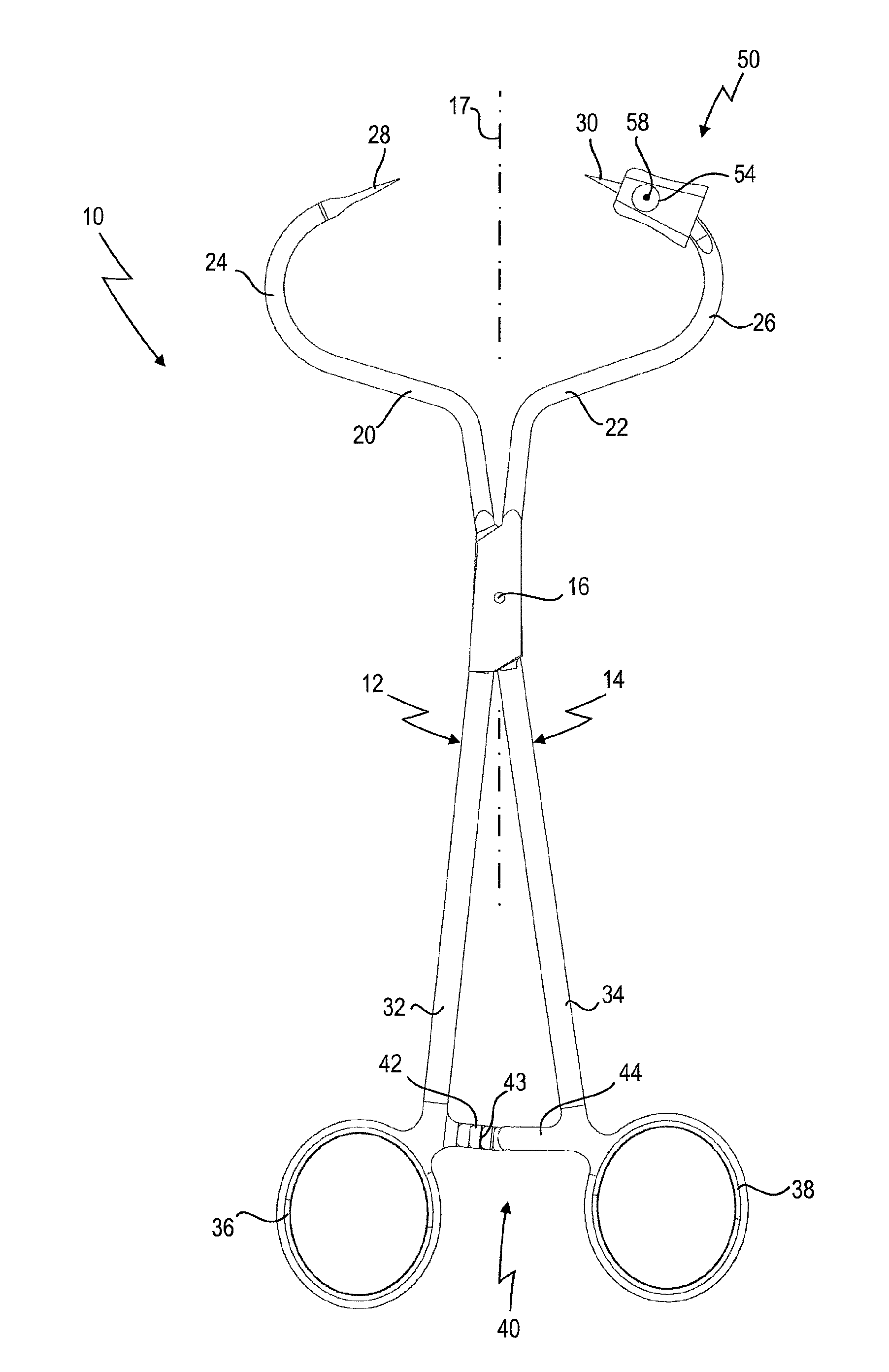
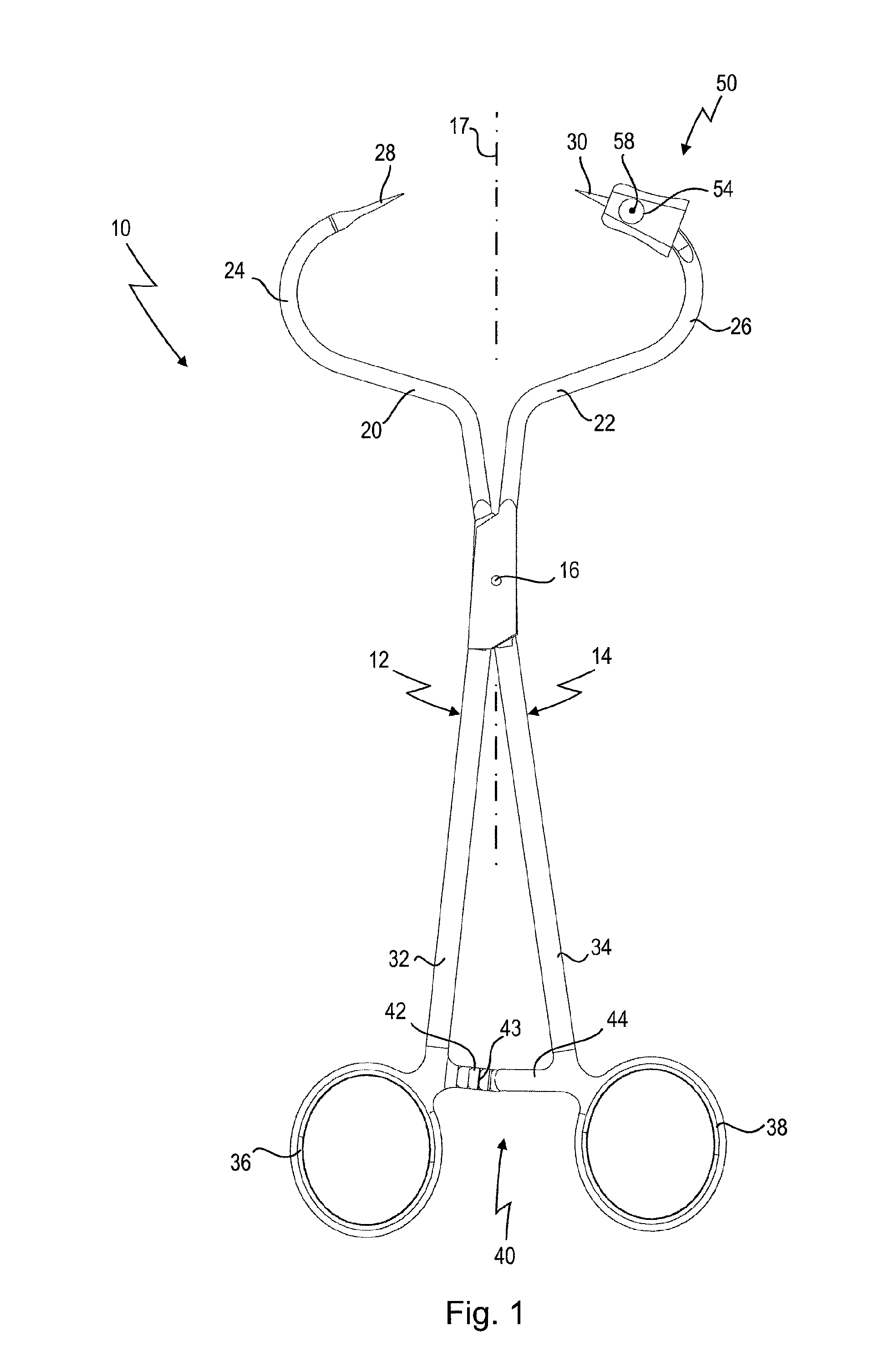
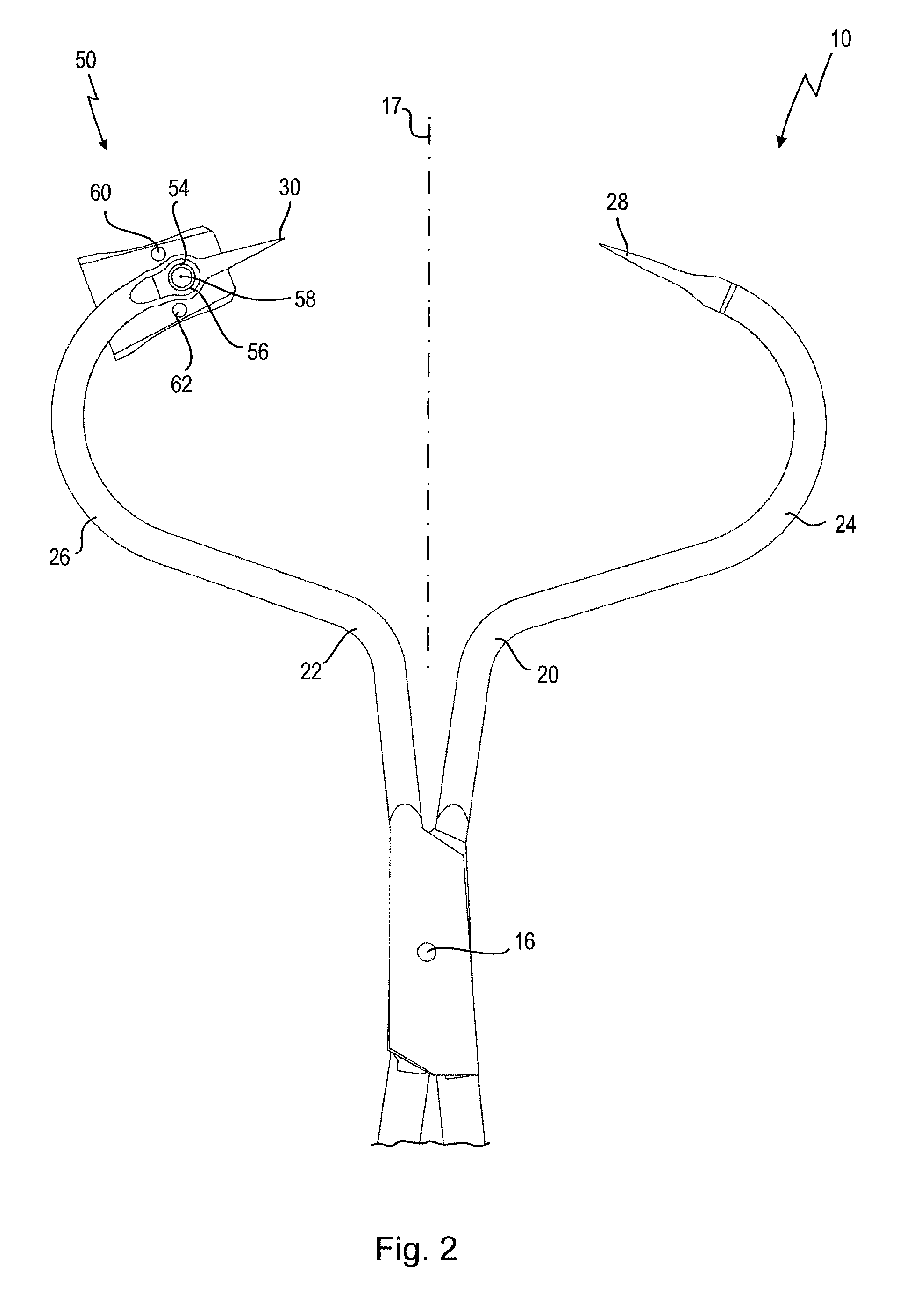
[0062]repositioning forceps according to the invention is shown in FIGS. 1 to 6 and is designated in its entirety by reference number 10.
[0063]The repositioning forceps 10 has two forceps halves 12 and 14, which are connected to each other like scissors via a hinge 16 and are pivotable about this hinge 16. It will be seen from FIG. 1 that the forceps halves 12 and 14, seen along a central longitudinal axis 17 of the repositioning forceps 10, are more or less mirror-inverted.
[0064]The two forceps halves 12 and 14 can thus be pivoted in a forceps plane 18, which in FIG. 1 corresponds approximately to the plane of the drawing.
[0065]In the distal direction from the hinge 16, each forceps half 12, 14 has a branch 20, 22, respectively.
[0066]Each of the branches 20, 22 has a laterally curved portion 24, 26, respectively, extending in the forceps plane 18.
[0067]The two curved portions 24, 26 each merge in the distal direction into an approximately rectilinear needle-like spike 28, 30, respe...
second embodiment
[0093]FIGS. 7a to 8 show a repositioning forceps which, as regards the actual body of the forceps, is constructed in the same way as the repositioning forceps 10 shown in FIG. 1.
[0094]In this illustrative embodiment too, a drilling aid is provided, which is designated in its entirety here by reference number 100 and which is mounted on a branch 104, wherein the branch 104 corresponds to the branch 22 in FIG. 1.
[0095]From the cross section, which runs transversely with respect to a central longitudinal axis 105 of the branch 104, it will be seen that the drilling aid 100 has a sleeve 102, which here engages completely around the body of the branch 104.
[0096]The sleeve 102 sits in a circumferential groove 106 on the outside of the branch 104. At the upper end shown in FIG. 7a or the end remote from the branch 104, a rotary stub 108 is introduced on which a guide block 110 of the drilling aid 100 is mounted rotatably.
[0097]The central longitudinal axis of the rotary stub 108 forms a ro...
third embodiment
[0107]In contrast to the second illustrative embodiment shown in FIGS. 7 and 8, the sleeve 122 in the drilling aid 120 is designed such that it engages completely around and bears on the outer face 124 of the branch 126, which again corresponds to the branch 22 of the illustrative embodiment in FIG. 1.
[0108]A securing device 128, for example in the form of a radially extending locking screw, is present in the branch 126 in order to fix a defined rotation position of the sleeve 122 about the longitudinal axis 132 of the branch 126. The central longitudinal axis of the branch 126 lies in the forceps plane 134 of the repositioning forceps.
[0109]Here too, a guide block 130 is mounted rotatably on the sleeve via a rotary stub, such that the guide block 130 can be rotated about a rotation axis 131 perpendicular to the forceps plane 134.
[0110]Extending through the guide block 130 is a continuous guide channel 132, which is not inclined, that is to say its central longitudinal axis extends ...
PUM
 Abstract
Description
Claims
Application Information