Gear ratio control method for continuously variable transmission of a vehicle

Active Publication Date: 2009-04-02
HONDA MOTOR CO LTD
View PDF3 Cites 20 Cited by
  • Summary
  • Abstract
  • Description
  • Claims
  • Application Information

AI Technical Summary

Benefits of technology

[0020]According to the present invention, the gear ratio is controlled at an engine rotary speed corresponding to the partially engaged state of the starting clutch. Therefore, for example, in the case where it is attempted to start the vehicle with a comparatively large throttle opening and it is intended to obtain a target engine rotary speed according to the throttle opening, it is possible in the partially engaged state to determine the gear ratio at a value corres

Problems solved by technology

However, there is the problem that when the starting clutch is engaged, the gear ratio position is at the LOW position, and due to the high driving force, the shock (due to engin

Method used


Image

  • Gear ratio control method for continuously variable transmission of a vehicle
  • Gear ratio control method for continuously variable transmission of a vehicle
  • Gear ratio control method for continuously variable transmission of a vehicle

Examples


Example

[0028]It should be understood that only structures considered necessary for illustrating selected embodiments of the present invention are described herein. Other conventional structures, and those of ancillary and auxiliary components of the system, will be known and understood by those skilled in the art.

[0029]Now, with reference to the accompanying drawings, a gear ratio control system for carrying out the gear ratio control method for a continuously variable transmission according to the present invention is described below.

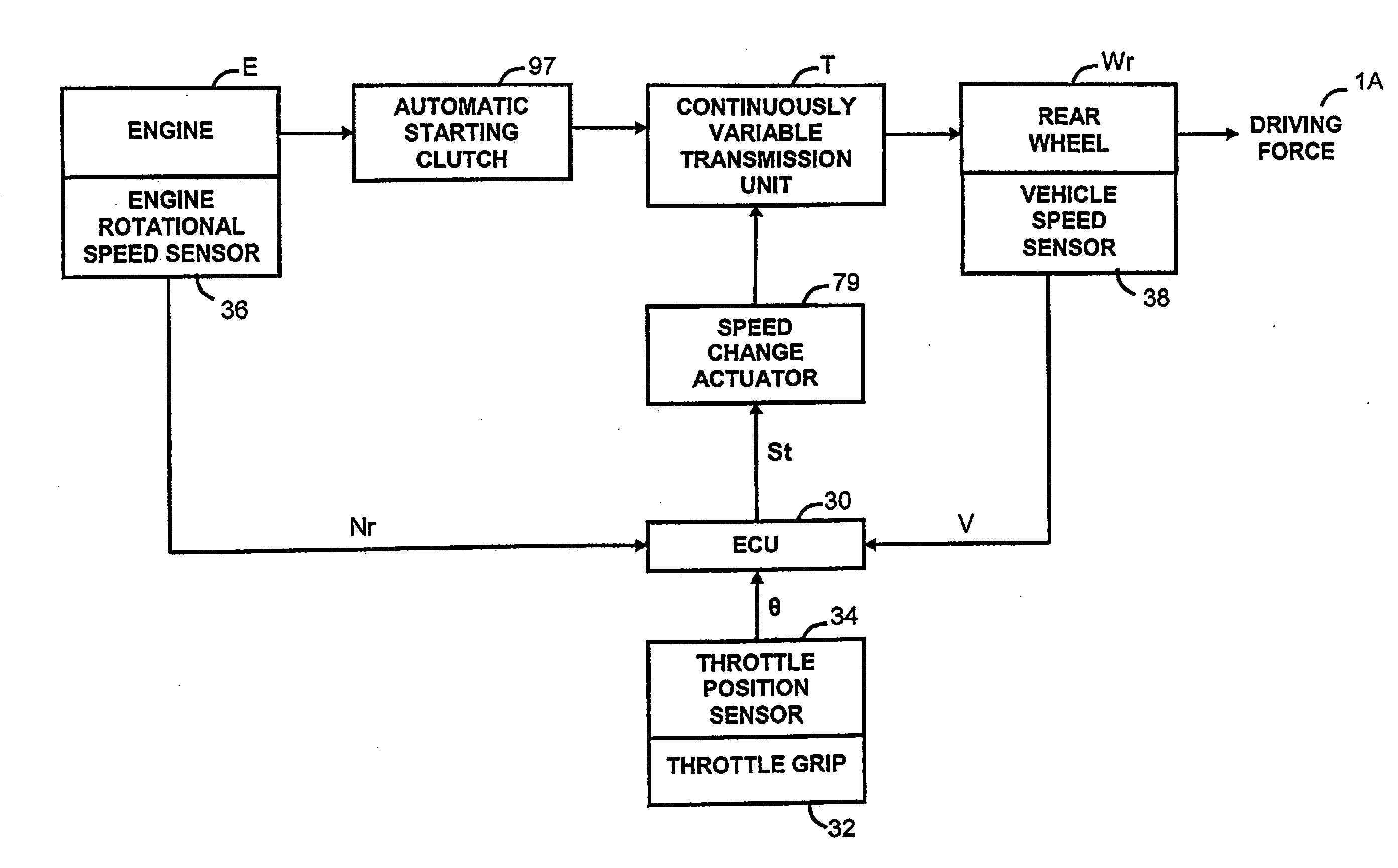
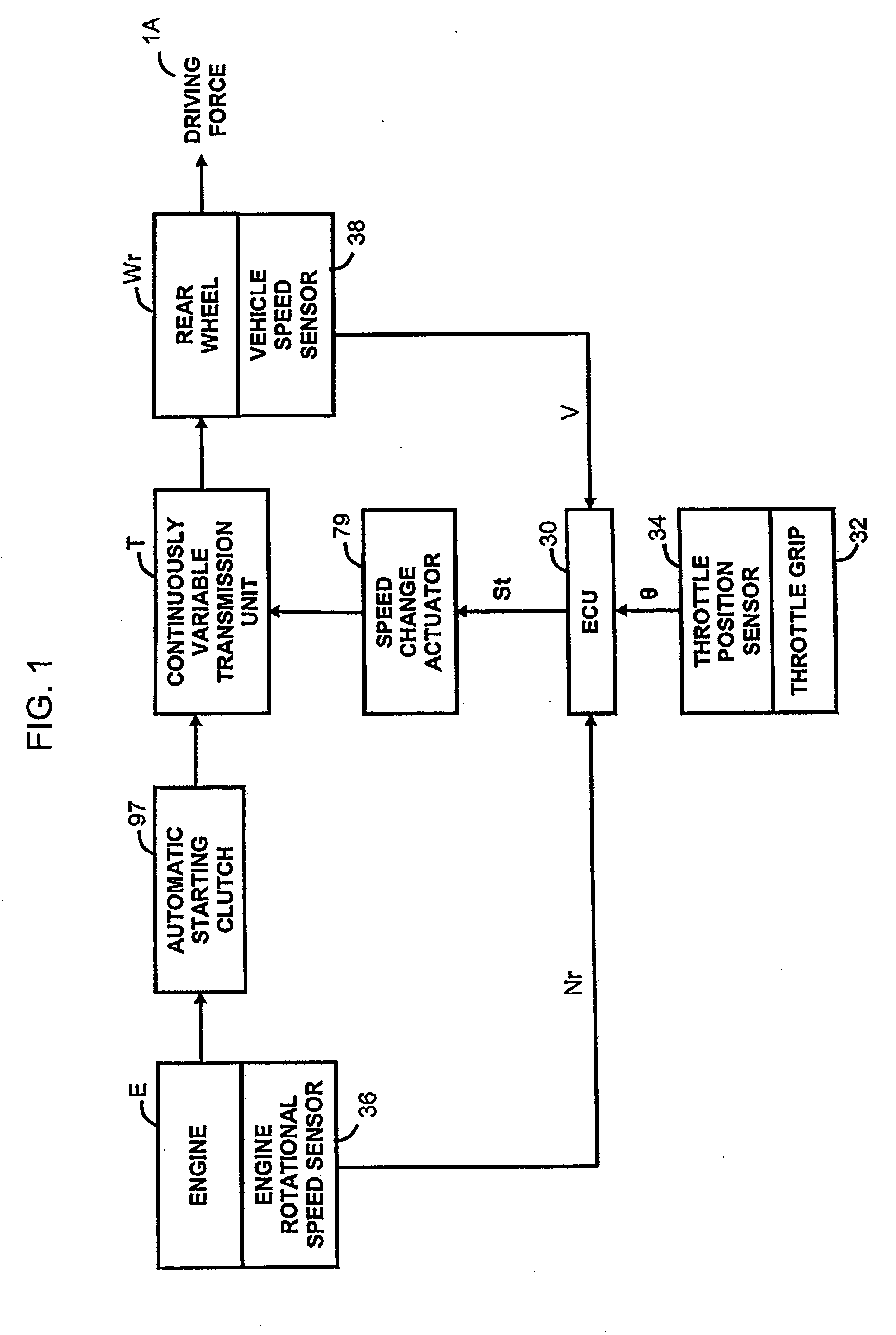
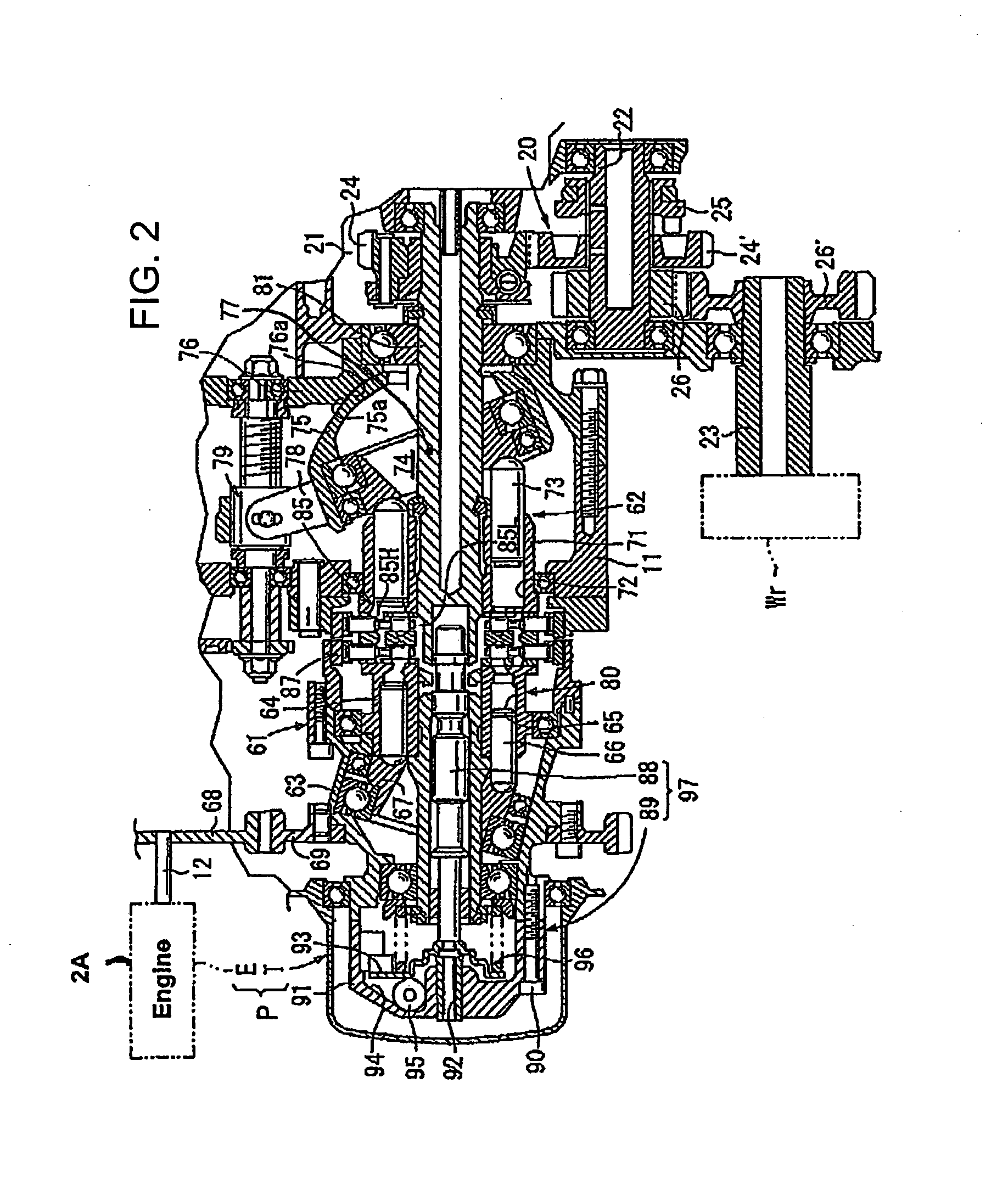
[0030]FIG. 2 is a partial longitudinal sectional view of a power unit P including a hydrostatic continuously variable transmission mountable on a vehicle such as a motorcycle. FIG. 1 is a generalized block diagram of the gear ratio control system 10 according to an illustrative embodiment for controlling the gear ratio in the hydrostatic continuously variable transmission (hereinafter referred to as the continuously variable transmission) shown in FIG. 2.

[003...


PUM


Abstract

At an actual engine rotary speed corresponding to a partially engaged state of a starting clutch, a target gear ratio control of a continuously variable transmission is performed by determining a target gear ratio from a target engine rotary speed. At an actual engine rotary speed corresponding to an engaged state of the starting clutch, the gear ratio is controlled in a manner such that the actual engine rotary speed converges with a target engine rotary speed. Accordingly, when it is intended to start the vehicle with a comparatively large throttle opening, it is possible, at the partially engaged condition, to obviate a rise in the actual engine rotary speed with the gear ratio position sticking to a desired position, so that a predetermined driving force is attained when the starting clutch is engaged.

Description

CROSS-REFERENCE TO RELATED APPLICATIONS[0001]The present application claims priority under 35 USC §119 based on Japanese patent application No. 2007-251623, filed on Sep. 27, 2007. The entire subject matter of this priority document is incorporated by reference herein.BACKGROUND OF THE INVENTION[0002]1. Field of the Invention[0003]The present invention relates to a gear ratio control method for a continuously variable transmission in a vehicle, in which a starting clutch is operable to automatically engage and disengage according to a rotary speed of an engine, and a continuously variable transmission unit is operable to continuous speed change according to the rotary speed of an input shaft; and in which, the starting clutch and the continuously variable transmission unit are connected in series between a crankshaft of the engine and an output shaft. More particularly, the present invention relates to a gear ratio control method for a continuously variable transmission in which a t...

Claims


Application Information

Patent Timeline
IPC IPC(8): F16H59/06G06F17/00
CPCB60W2510/0241F16H61/4043F16H2312/02F16H61/462F16H61/425
Inventor USUKURA, YASUTAKA
Owner HONDA MOTOR CO LTD
Why Eureka
Try Eureka