System and Method for Generating Steam Using a Solar Power Source in Conjunction with a Geothermal Power Source

a solar power source and power generation technology, applied in solar heat storage, machines/engines, light and heating apparatus, etc., can solve the problems of dsg systems having their own drawbacks, solar collectors, and relatively low energy density of fluid, so as to minimize the added cost and safety concerns associated, the effect of superior heat transfer capability of water and superior energy carrying capacity

Inactive Publication Date: 2012-05-24
US MICROPOWER
View PDF9 Cites 15 Cited by
  • Summary
  • Abstract
  • Description
  • Claims
  • Application Information

AI Technical Summary

Benefits of technology

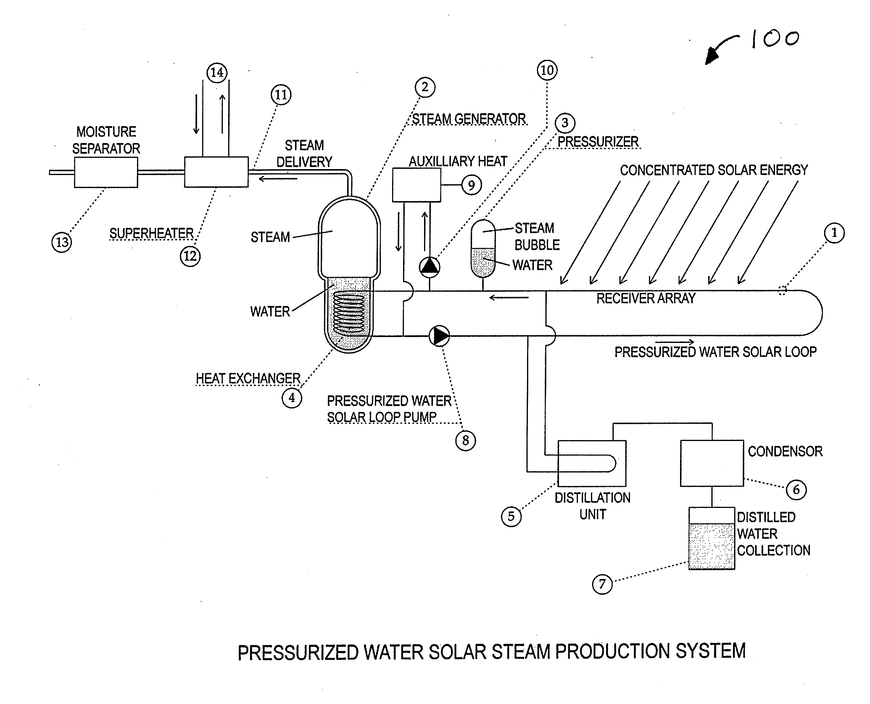
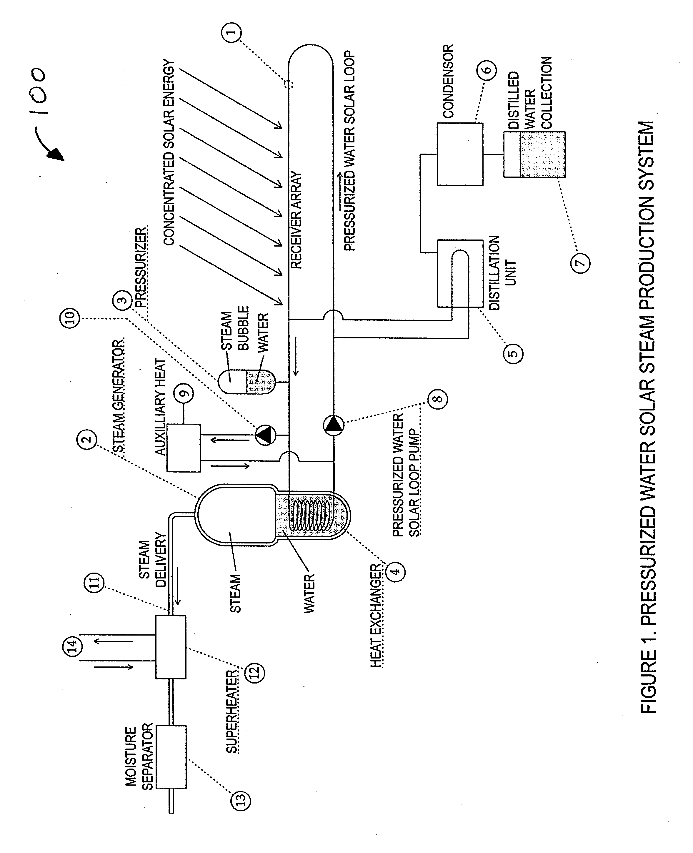
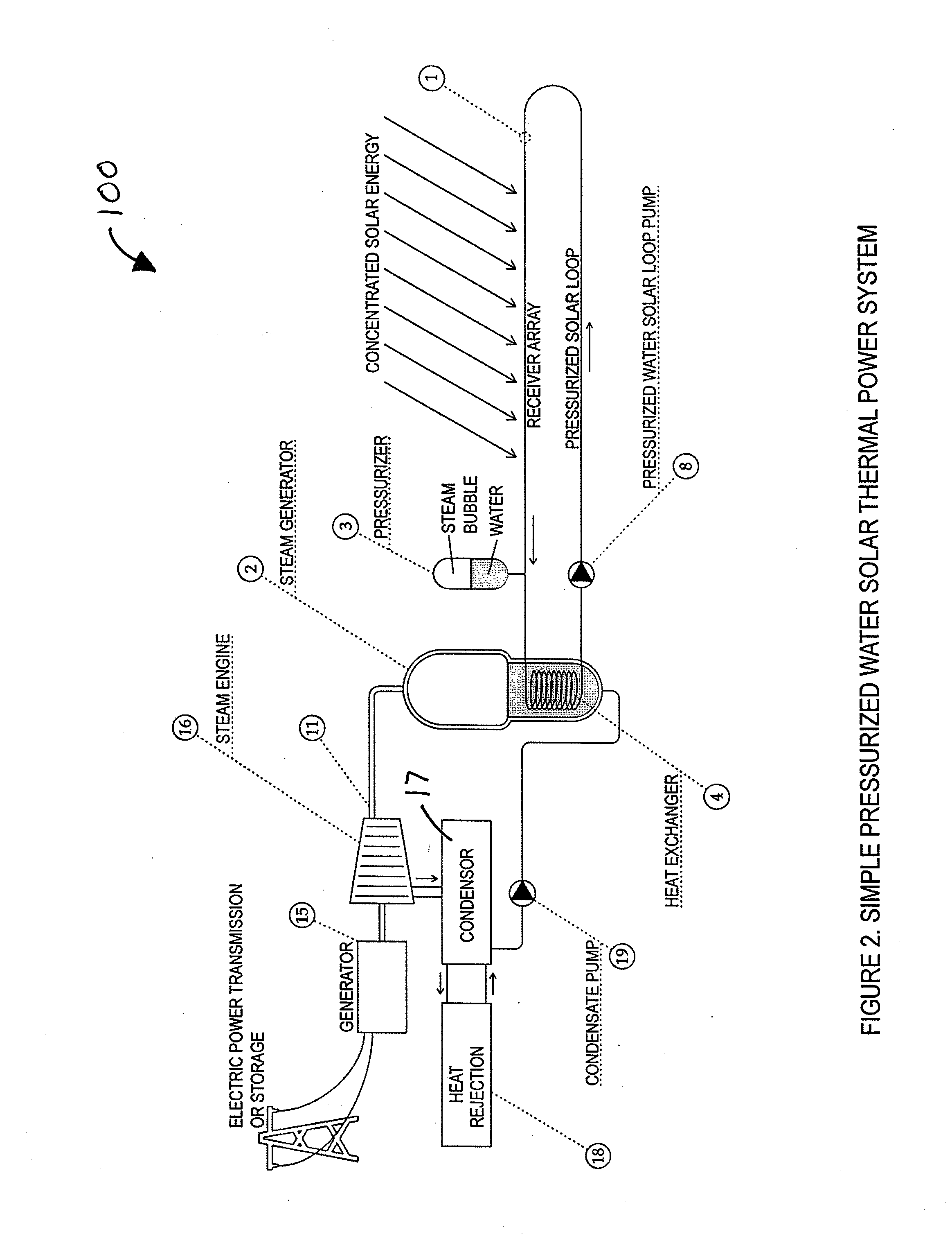
[0008]Disclosed herein are systems and methods for generating electrical power using a solar power system comprising pressurized pipes for transporting liquid water. The pressurized pipes flow through solar collectors which concentrate sunlight on the water flowing through said pipes. Because the pipes inside the solar collectors are pressurized, the water flowing therethrough can be heated well above the ordinary boiling point of water (100° C.). Advantageously, the systems and methods described herein rely upon the superior heat transfer capabilities of water in comparison to synthetic heat transfer fluids. Furthermore, the lack of synthetic heat transfer fluid minimizes the added costs and safety concerns associated with the use of such fluids.
[0009]Finally, the pressurized pipes described herein prevent the water flowing therethrough from flashing over to steam when heated to a high temperature. Accordingly, the instabilities and unwanted pressure drops associated with two-phase (water / steam) flow are eliminated. Furthermore, the use of water rather than steam for transporting thermal energy takes advantage of water's superior energy carrying capacity in comparison to steam.

Problems solved by technology

One disadvantage of the use of a synthetic heat transfer fluid is that the fluid has a relatively low energy density.
Another disadvantage of synthetic heat transfer fluids is that they are often flammable.
Such DSG systems have their own drawbacks, however.
First, the presence of steam in the pipes of the solar collectors reduces the efficiency of the collectors because steam has a significantly lower heat capacity than water.
Finally, DSG systems are more sensitive to variations in solar flux density and changes in atmospheric conditions because the systems will not function properly unless the water in the solar collectors is sufficiently heated to flash over to steam.
Taken together, these drawbacks necessitate the use of larger, more expensive solar collectors to produce a given amount of electricity.
Therefore, such DSG systems may have little or no cost savings in comparison to traditional CSP systems containing synthetic heat transfer fluid.

Method used


Image

  • System and Method for Generating Steam Using a Solar Power Source in Conjunction with a Geothermal Power Source
  • System and Method for Generating Steam Using a Solar Power Source in Conjunction with a Geothermal Power Source
  • System and Method for Generating Steam Using a Solar Power Source in Conjunction with a Geothermal Power Source

Examples


second embodiment

[0029]Turning to FIG. 3, a pressurized solar power system 200 is shown. The embodiment shown in FIG. 3 is similar in many respects to the embodiment shown in FIGS. 1-2, with like reference numerals indicating like parts between the two embodiments. The pressurized solar power system 200 of FIG. 3 generally comprises a pressurized solar loop 1 that preferably contains pressurized water. The pressurized water in solar loop 1 absorbs thermal energy from the concentrated solar energy produced by one or more solar collectors and transports said thermal energy to a heat exchanger 104.

[0030]Heat exchanger 104 preferably comprises two vessels: a pressurized steam generator vessel 102 and a non-pressurized storage media vessel 103. The storage media vessel 103 contains a substance suitable for storing and transporting thermal energy such as molten salt. The steam generator vessel 102 contains water in the lower portion of the vessel 102 which, when heated sufficiently, will boil and produce ...

third embodiment

[0036]Turning to FIG. 5, a pressurized solar power system 300 is shown. The embodiment shown in FIG. 5 is similar to the embodiment shown in FIG. 3, with like reference numerals indicating like parts between the two embodiments. The pressurized solar power system 300 comprises an array of solar collectors (solar array), a pressurized solar loop 1, a heat exchanger 104, a steam turbine 16, and an electric generator 15. The heat exchanger 104 comprises a steam generator vessel 102 and a storage media vessel 101 and functions in a manner similar to the heat exchanger 104 of FIG. 3.

[0037]The pressurized solar power system 300 in FIG. 5 is shown operating in conjunction with a geothermal power source or energy 301 and a natural gas source 311. Hot water, steam, natural gas, and / or other carriers or forms of geothermal substances from the geothermal power source 301 are directed to a separation tank 302 where natural gas can be separated from the hot water generated by the geothermal powe...


PUM


Abstract

System and method for generating electrical power using a solar power system comprising pressurized pipes for transporting liquid water in conjunction with a geothermal power source. The pressurized pipes flow through solar collectors which concentrate light on the water flowing through the pipes. The pressurization in the pipes allows for the water to absorb large quantities of energy. The pressurized and heated water is then pumped to a heat exchanger where the thermal energy is released to produce steam for powering a steam turbine electrical generator. Thereafter, the water is returned to the solar collectors in a closed loop to repeat the process. In conjunction with the solar power system, heated water from the geothermal power source is directed through a second pipe that also traverses the heat exchanger to assist in the production of steam for powering the turbine electrical generator.

Description

CROSS-REFERENCE TO RELATED APPLICATIONS[0001]This application is a divisional application of U.S. patent application Ser. No. 12 / 870,202, filed on Aug. 27, 2009 and currently pending, which claims priority to U.S. provisional application No. 61 / 237,769, filed Aug. 28, 2009, each application being incorporated herein by reference.BACKGROUND OF THE INVENTION[0002]Large scale solar power plants utilizing concentrating solar power (“CSP”) technology have been in production for over twenty years. The Solar Electric Generating Systems (“SEGS”) facilities in the Mojave Desert of California are a well-known example of solar power plants using such CSP technology. Concentrating solar power utilizes solar collectors comprising large mirrors or lenses which concentrate solar energy upon an unpressurized pipe or tube that contains a heat transfer fluid. Typically, a synthetic oil having a high boiling point is used as the heat transfer fluid. For example, the SEGS facilities utilize Therminol® ...

Claims


Application Information

Patent Timeline
Patent Type & Authority Applications(United States)
IPC IPC(8): F03G4/00F03G6/00F24S10/30F24S20/20
CPCF03B17/00F24J2/07Y02E10/41Y02E10/46Y02E10/10F03G6/067F24S60/30F24S20/40F24S20/20F24S10/30F24S60/10Y02E10/20Y02E10/44F03G6/005Y02E10/40F03G6/063F03G4/037F03G6/061F03G6/062F01K7/16
Inventor NEWMAN, MICHAEL
Owner US MICROPOWER
Why Eureka
Try Eureka