Multi-stage voltage regulating circuit with automatic thermal compensation and regulating method thereof

a voltage regulating circuit and multi-stage technology, applied in the direction of power conversion systems, instruments, apparatus without intermediate ac conversion, etc., can solve the problems of difficult to lower the cost of the voltage regulating circuit, ineffective function of the liquid crystal display panel, and limited improvement of function, so as to achieve high effective function and reduce manufacturing costs

Inactive Publication Date: 2012-05-24
RICHTEK TECH
View PDF4 Cites 8 Cited by
  • Summary
  • Abstract
  • Description
  • Claims
  • Application Information

AI Technical Summary

Benefits of technology

[0017]It can be understood from the foregoing that the multi-stage voltage regulating circuit and method with automatic temperature compensation according to the present invention are capable of lowering the manufacturing cost because no inductors and p...

Problems solved by technology

However, it causes that the function of the liquid crystal display panel becomes ineffective after the operation temperature being increased although increasing the voltage of the power is able to solve the problem of starting the liquid crystal display panel at the low temperature.
Nevertheless, the boost-type voltage regulating circuit with automatic temperature compensation as s...

Method used


Image

  • Multi-stage voltage regulating circuit with automatic thermal compensation and regulating method thereof
  • Multi-stage voltage regulating circuit with automatic thermal compensation and regulating method thereof
  • Multi-stage voltage regulating circuit with automatic thermal compensation and regulating method thereof

Examples


Embodiment Construction

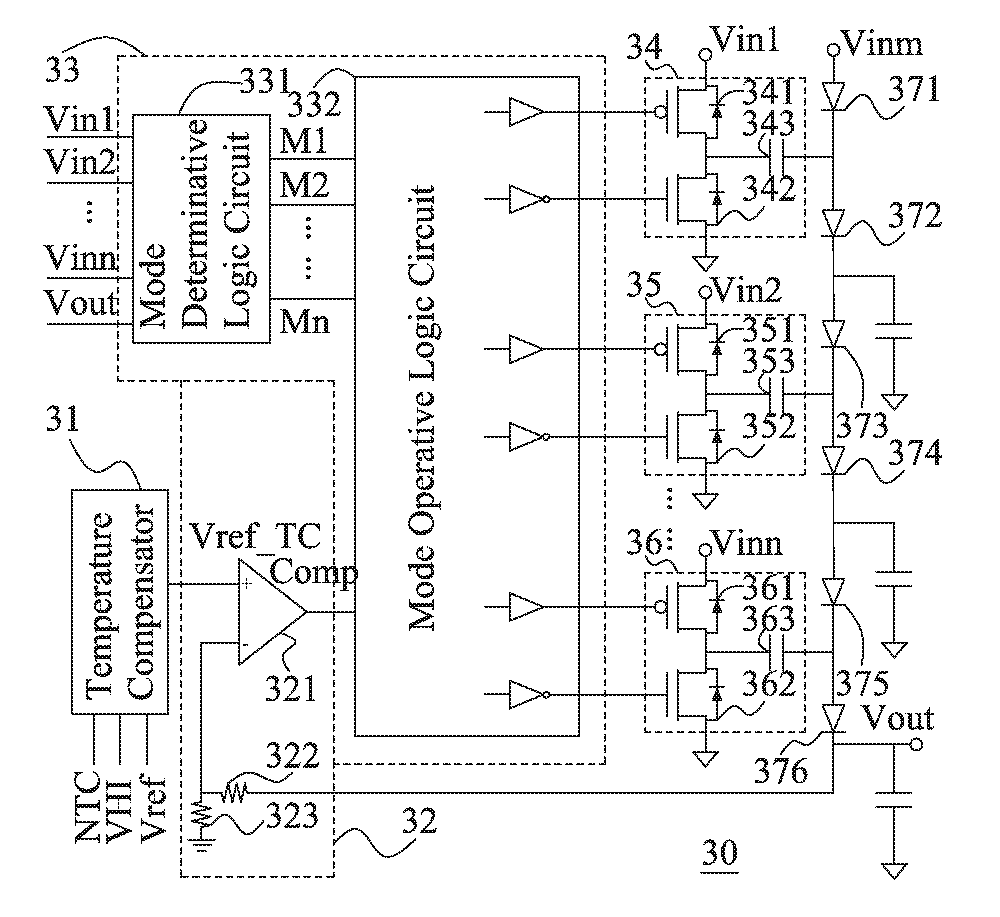
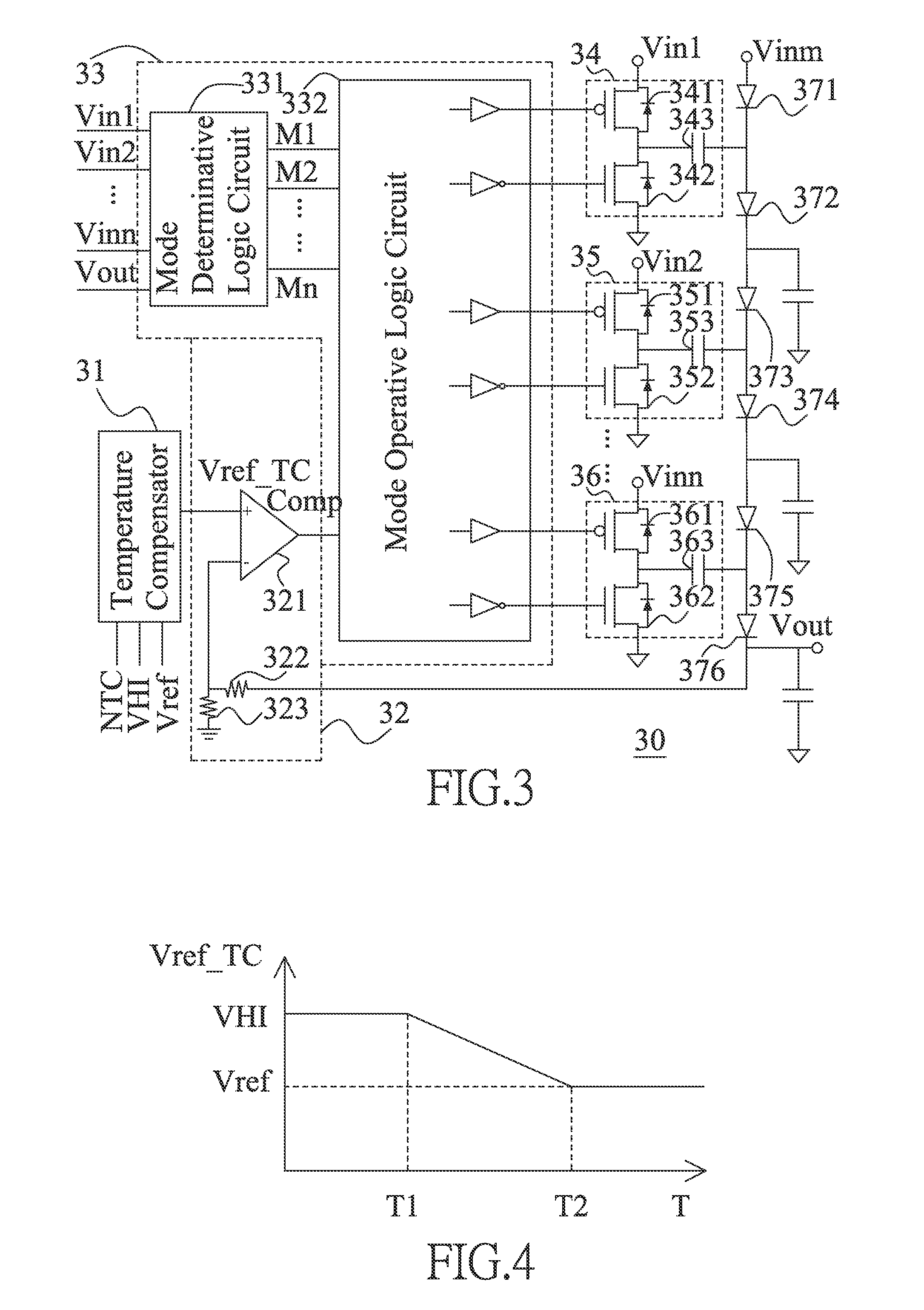
[0024]Referring to FIG. 3, a preferred embodiment of a multi-stage voltage regulating circuit with automatic thermal compensation according to the present invention is illustrated. The multi-stage voltage regulating circuit with automatic thermal compensation 30 is suitable for regulating voltage of the output power source Vout automatically based on a detected ambient temperature.

[0025]It can be seen in FIG. 3 that the multi-stage voltage regulating circuit with automatic thermal compensation 30 includes a plurality of charge-pumps 34, 35, . . . , 36, a temperature compensator 31, a comparative unit 32, and a control logic circuit 33. The control logic circuit 33 further has a mode determinative logic circuit 331 and a mode operative logic circuit 332.

[0026]Wherein, the charge-pump 34 consists of a switch set composed of a PMOS transistor 341 and an NMOS transistor 342 connecting with each other in series and a capacitor 343 connecting with a connecting node between the PMOS transi...


PUM


Abstract

A multi-stage voltage regulating circuit and method with automatic temperature compensation comprises a plurality of charge-pumps, a temperature compensator, a comparative unit and a control logic circuit; wherein, the temperature compensator detects the ambient temperature and outputs a reference voltage related to the ambient temperature, the comparative unit compares the voltage of the output power source to the reference voltage output by the temperature compensator and outputs a comparative signal based on the comparison, and the control logic circuit controls the charging/discharging operations of the charge-pumps based on the comparative signal and voltages of input power sources connected to said charge-pumps to automatically regulate the voltage of the output power source.

Description

BACKGROUND OF THE INVENTION[0001]1. Field of the Invention[0002]The present invention is related to a voltage regulator circuit and particularly to a multi-stage voltage regulating circuit with automatic thermal compensation and a multi-stage voltage regulating method thereof.[0003]2. Brief Description of the Related Art[0004]The voltage regulator circuit is used for supplying the power required by a liquid crystal display panel. Because a gate-on voltage of the thin film transistor (TFT) in the liquid crystal display panel increases with a decreasing temperature, the voltage of the power of the liquid crystal display panel has to be increased in order to maintain a normal operation of the liquid crystal display panel in an environmental of low temperature. However, it causes that the function of the liquid crystal display panel becomes ineffective after the operation temperature being increased although increasing the voltage of the power is able to solve the problem of starting th...

Claims


Application Information

Patent Timeline
IPC IPC(8): G05F1/10
CPCH02M2001/0025H02M3/07H02M1/0025G05F1/567
Inventor WANG, DER-JIUNNTSAI, KUO-CHEN
Owner RICHTEK TECH
Why Eureka
Try Eureka