
Applicator For Cosmetic Product

a cosmetic product and application technology, applied in the field of cosmetic product applications, can solve the problems of tendency to deform under tautness and do not allow and achieve the effect of more uniform application of cosmetic products

Active Publication Date: 2012-05-24
ALBEA SERVICES SAS
View PDF7 Cites 15 Cited by
  • Summary
  • Abstract
  • Description
  • Claims
  • Application Information

AI Technical Summary

Benefits of technology

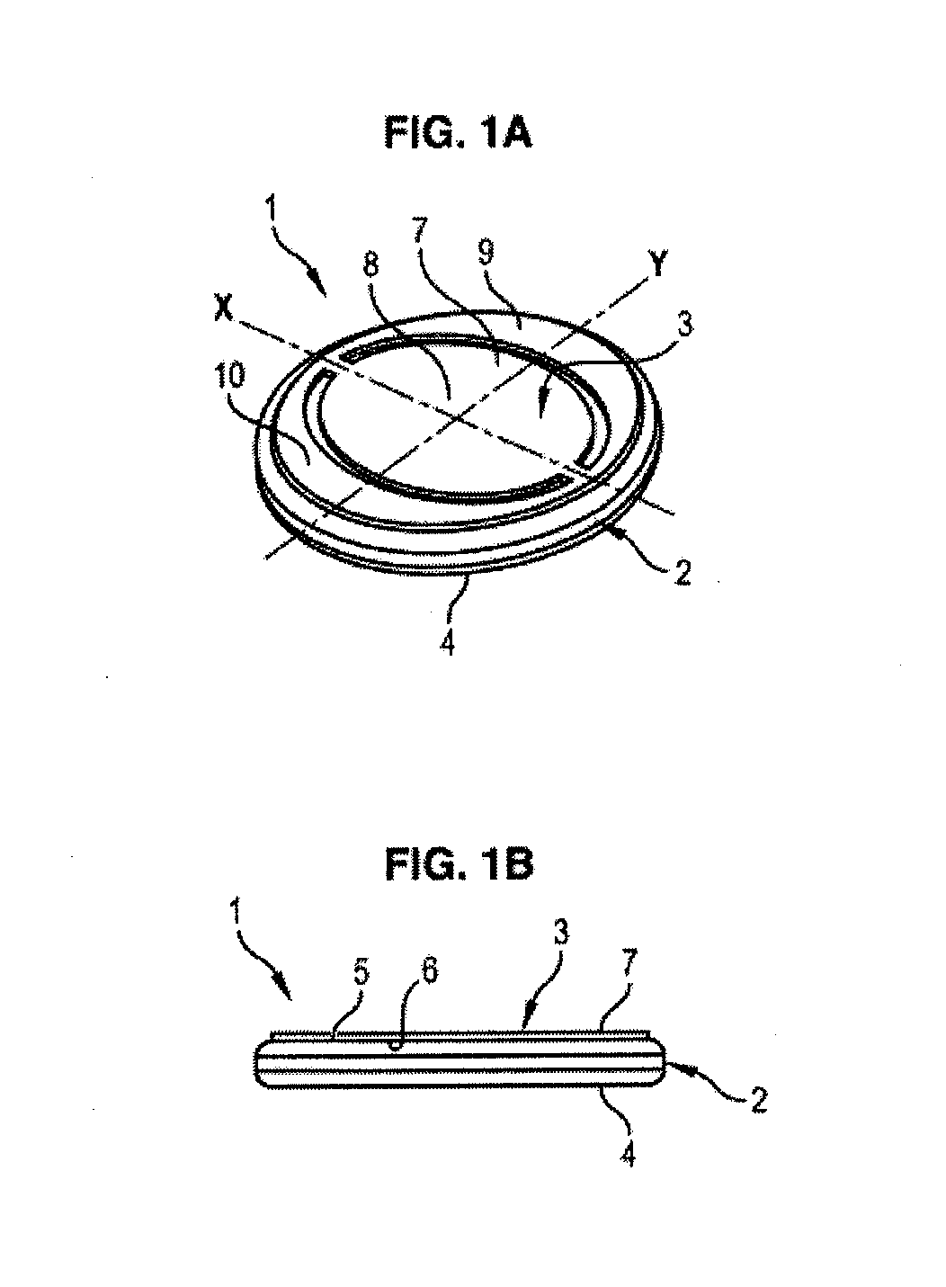
[0006]It is one objective of the invention to propose an applicator for cosmetic product which is both compact so that it can be housed in a case, and also allows more uniform application of the cosmetic product.
[0011]In said applicator, since the support element is formed from a planar blank it can easily be housed in a case.
[0012]In addition, the support element allows rigidity to be imparted to the applicator to support the pad element during application of the cosmetic product.

Problems solved by technology

One drawback of these applicators is that they have a tendency to deform under a tautening effect exerted by the ribbon when the user takes hold of this ribbon.
On this account, these applicators do not allow uniform application of the cosmetic product.

Method used


Image

  • Applicator For Cosmetic Product
  • Applicator For Cosmetic Product
  • Applicator For Cosmetic Product

Examples


second embodiment

[0055]FIGS. 7A and 7B schematically illustrate an applicator 1 conforming to the invention.

[0056]In this second embodiment, the pad element 2 and the support element 3 have a general, substantially square shape.

third embodiment

[0057]FIGS. 8A and 8B schematically show an applicator 1 conforming to the invention.

[0058]In this third embodiment, the pad element 2 is of circular disc shape whilst the support element 3 is shaped with two lobes 24 and 25 arranged either side of the axis X. The cut-outs 11 and 12 follow the shape of the edge of the support element 3, so that the main region 13 of the central portion 8 also has two lobes extending either side of the axis X and flaring outwardly from this axis.

fourth embodiment

[0059]FIGS. 9A and 9B schematically illustrate an applicator 1 conforming to the invention.

[0060]In this fourth embodiment, the pad element 2 and the support element 3 are of substantially circular shape.

[0061]In addition, the support element 3 comprises a substantially circular, central attached portion 8 in which a central opening 26 is formed. The central opening 26 has a circular shape centred on the axes X and Y. In this manner, the central portion 8 is of general annular shape.

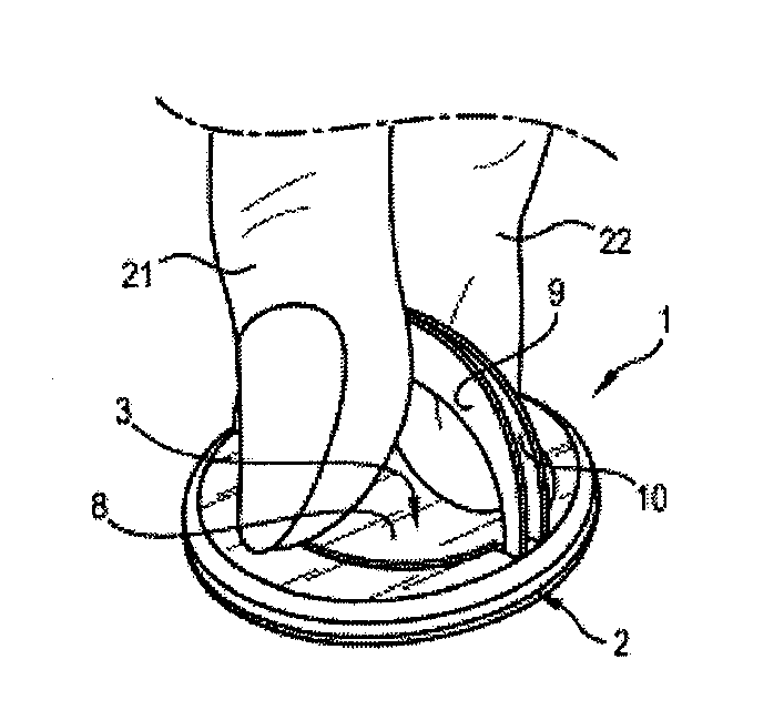
[0062]The central opening 26 allows flexibility to be imparted to a central part of the applicator, whilst the peripheral part of the applicator around the central part is maintained planar. The user can take hold of the applicator 1 as illustrated in FIG. 6 so as to position the tip of the finger at the central opening 26 in contact with the side 5 of the pad element. This enables the user to exert pressure directly on the pad element 2 through the opening 26 so that it is possible for example to apply ...


PUM

PropertyMeasurementUnit
Thicknessaaaaaaaaaa
Flexibilityaaaaaaaaaa
Shapeaaaaaaaaaa

Abstract

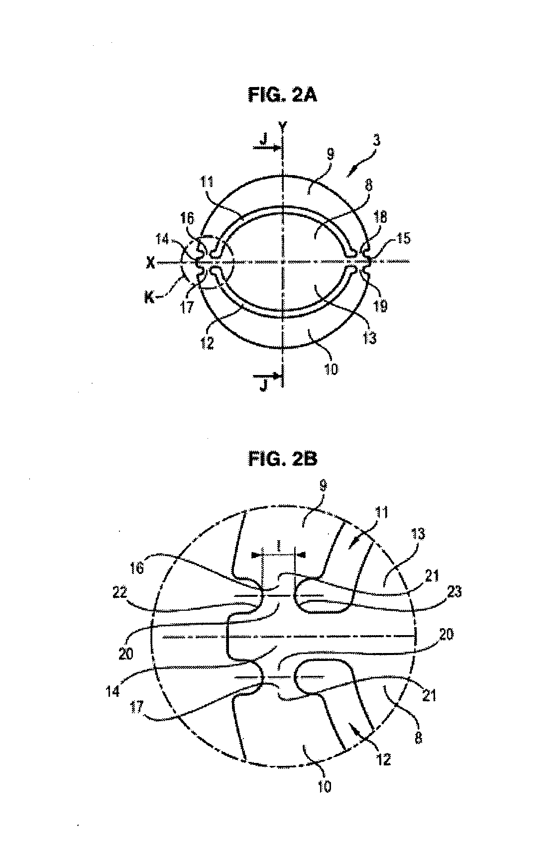
The invention concerns an applicator (1) for cosmetic product, comprising:a pad element (2) having a first side for application of the cosmetic product and a second side opposite the first side, anda support element (3) comprising a central attached portion (8) and two side grasping portions (9, 10) arranged either side of the central attached portion (8), the central attached portion (8) being attached onto the second side (5) of the pad element (2),wherein the support element (3) is formed from a planar blank having two slots, each slot forming a space separating the central attached portion (8) from a side grasping portion (9, 10).

Description

FIELD OF THE INVENTION[0001]The invention concerns an applicator for a cosmetic product.STATE OF THE ART[0002]Applicators of<<powder puff>>type are known comprising a pad or soft sponge that is disc-shaped. These applicators are particularly adapted to be housed in cases containing a cosmetic product such as compact powder for example.[0003]These applicators can be provided with a ribbon of which each end is attached close to the circumference of the pad. The ribbon forms grasping means enabling the user to slide fingers between the ribbon and the pad so as to grasp the applicator in order to take up and apply the cosmetic product.[0004]One drawback of these applicators is that they have a tendency to deform under a tautening effect exerted by the ribbon when the user takes hold of this ribbon.[0005]On this account, these applicators do not allow uniform application of the cosmetic product.SUMMARY OF THE INVENTION[0006]It is one objective of the invention to propose an a...

Claims


Application Information

Patent Timeline
IPC IPC(8): A45D33/36
CPCA45D33/34A45D2200/1018A45D33/36
Inventor LIMONGI, MICHELLEQUEUX, VINCENT
Owner ALBEA SERVICES SAS
Learn More