
Methods and Systems for Filtering Traffic Information for Display

a technology of traffic information and filtering method, applied in the field of system and method for displaying traffic information, can solve problems such as display unusability

Active Publication Date: 2012-05-24
THE BOEING CO
View PDF11 Cites 38 Cited by
  • Summary
  • Abstract
  • Description
  • Claims
  • Application Information

AI Technical Summary

Benefits of technology

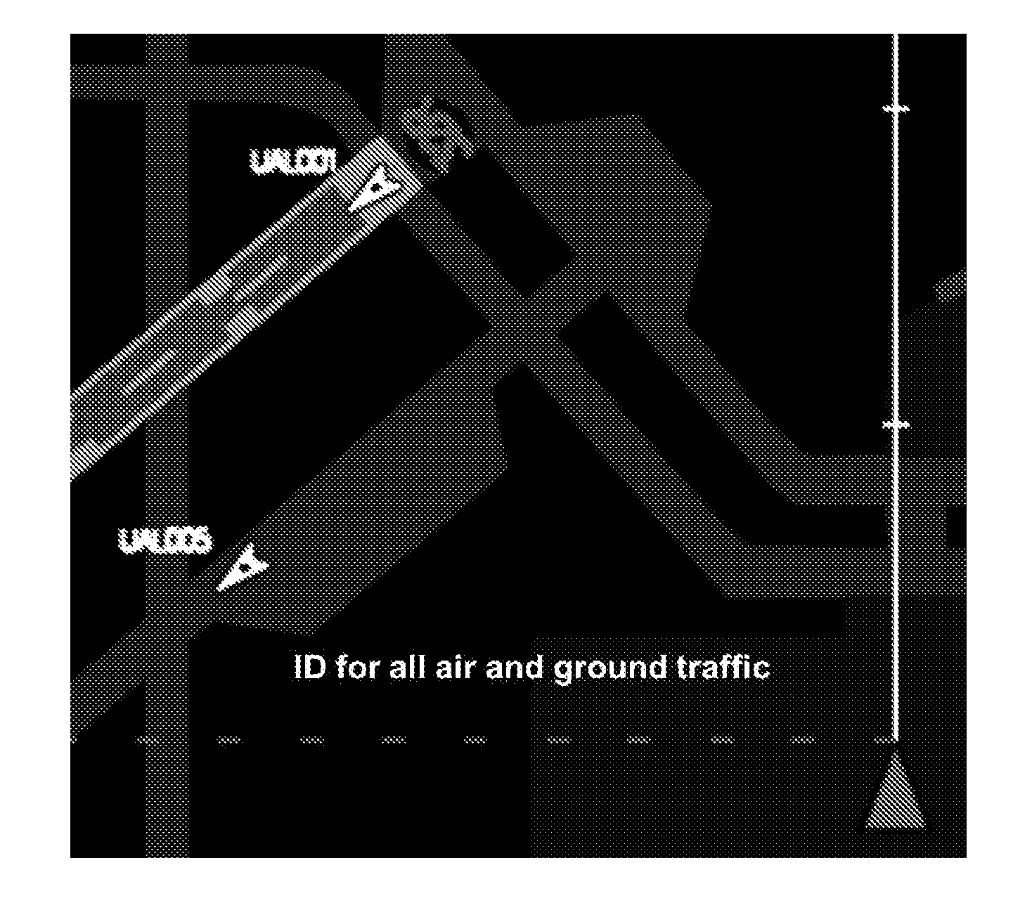
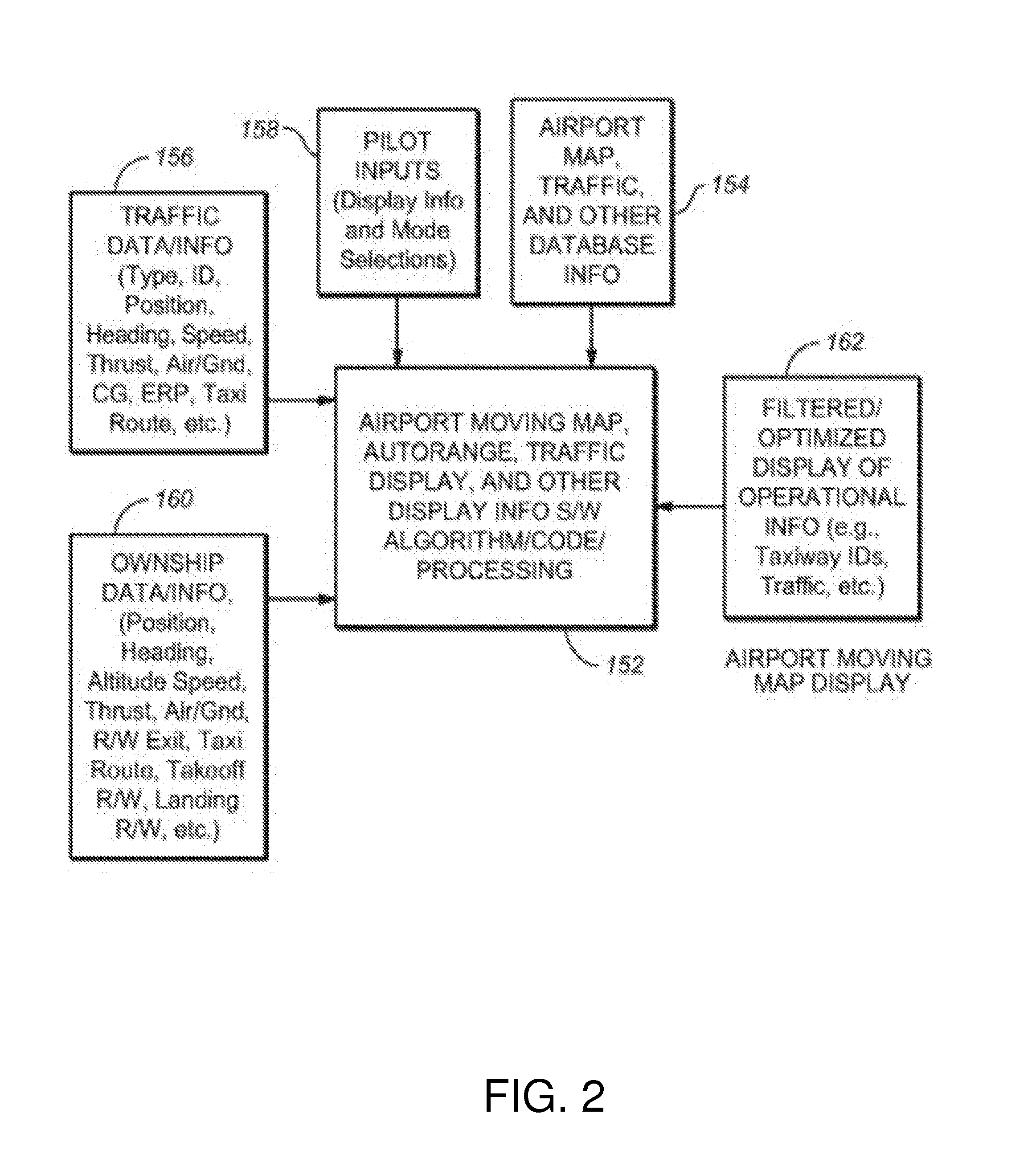
The patent describes an electronic airport moving map system that displays traffic data for taxiing, takeoff / departure, and approach / landing within an airport traffic zone. The system uses a traffic switch to determine which traffic symbols and data to display based on the state of the switch. When the ownship speed is less than or equal to a certain threshold, the system displays all air and ground traffic based on TCAS filtering rules. When the ownship speed is greater than a certain threshold, the system displays air traffic and ground traffic based on the same rules, but no traffic data is displayed. The system can also display a groundspeed datum for all traffic in the ground runway operating zone and a distance from the ownship. The technical effect of this patent is to provide a more efficient and effective tool for airport traffic control and management.

Problems solved by technology

Further, the manual setting of the display range may preclude display of traffic, areas or other objects of interest, or other information within or beyond the display range of the EAMM that may be important to safety and / or situational awareness.
The display of all traffic symbology and data on an airport or runway moving map can result in clutter that makes the display unusable at the display ranges used during taxi, takeoff and approach / landing.
This clutter results from the typical map display scales / ranges of 0.5 to 10 nm and the large numbers of aircraft and vehicles on the airport available for display.

Method used


Image

  • Methods and Systems for Filtering Traffic Information for Display
  • Methods and Systems for Filtering Traffic Information for Display
  • Methods and Systems for Filtering Traffic Information for Display

Examples


Embodiment Construction

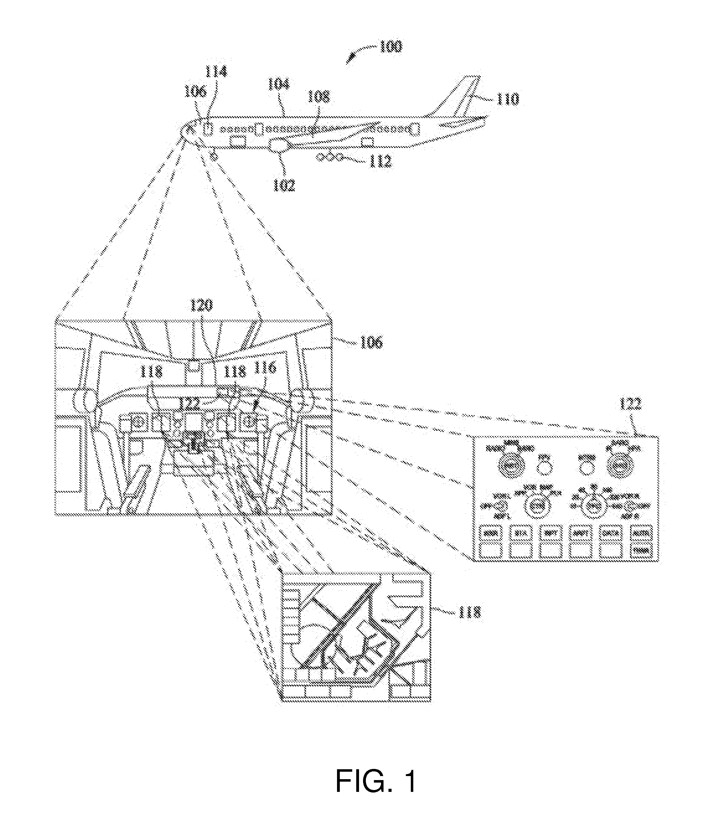
[0027]FIG. 1 is a side elevational view of a vehicle 100 such as an aircraft in accordance with one embodiment. Aircraft 100 includes one or more propulsion engines 102 coupled to a fuselage 104, a cockpit 106 in fuselage 104, wing assemblies 108, a tail assembly 110, a landing assembly 112, a control system (not visible), and a plurality of other systems and subsystems that enable proper operation of vehicle 100. At least one component of an EAMM system 114, configured in accordance with the present disclosure, is located within fuselage 104. However, components of EAMM system 114 may be distributed throughout the various portions, systems and subsystems of vehicle 100 and other components may also be located off board vehicle 100 and in communication with the onboard components.

[0028]Although vehicle 100 shown in FIG. 1 is generally representative of a commercial passenger aircraft, the inventive systems and methods disclosed herein may also be employed in virtually any other type...


PUM


Abstract

A method and a system for displaying an airport or runway moving map with traffic information on a display screen in the cockpit or flight deck of an aircraft. Symbology representing surface and near-surface aircraft and surface vehicle traffic and associated traffic data are filtered to prevent or limit clutter on the display screen. Traffic symbology is automatically and manually filtered to display only relevant traffic. Traffic data is selectively displayed and displayed as / when relevant or needed. The displayed traffic information may be derived from automatic dependent surveillance-broadcast, traffic information system-broadcast, automatic dependent surveillance-rebroadcast, traffic collision avoidance system or other source.

Description

RELATED PATENT APPLICATION[0001]This application is a continuation-in-part of and claims priority from U.S. patent application Ser. No. 11 / 939,806 filed on Nov. 14, 2007 and entitled “Multi-Function Switches for a Display”.BACKGROUND[0002]The invention generally relates to systems and methods for displaying traffic information on a map. In particular, the disclosed embodiments relate to systems and methods for filtering the traffic information in order to prevent or limit clutter on a display screen.[0003]Modern aircraft typically include cockpit displays that are controlled by an information system. Cockpit displays include the basic displays that are supplied with the aircraft, and other add-on displays which vary in their degree of integration with the physical aircraft structure and aircraft systems. In addition, some known aircraft include displays which provide a “virtual” display-based interface through which the crew controls aircraft systems.[0004]To promote safety and effi...

Claims


Application Information

Patent Timeline
Patent Type & Authority Applications(United States)
IPC IPC(8): G08G5/00G08G5/06
CPCG01C23/00G08G5/065G08G5/0078G08G5/0021
Inventor CLARK, SAMUEL T.BOWE, ROGLENDA R.ORTMAN, STEPHEN BERNARDCRANE, JEAN MARIE
Owner THE BOEING CO
Learn More