
Back end of payment system associated with financial transactions using card readers coupled to mobile devices

Active Publication Date: 2012-05-24
BLOCK INC
View PDF48 Cites 117 Cited by
  • Summary
  • Abstract
  • Description
  • Claims
  • Application Information

AI Technical Summary

Benefits of technology

[0015]A further object of the present invention is to provide methods utilizing card readers with increased efficiency for financial transactions using mobile devices.

Problems solved by technology

Although magnetic stripe cards are universally used by merchants, there is no way for an individual to take advantage of the card to receive a payment from another individual (who is not a merchant) by swiping the card through a simple reader attached to his / her mobile device.

Method used


Image

  • Back end of payment system associated with financial transactions using card readers coupled to mobile devices
  • Back end of payment system associated with financial transactions using card readers coupled to mobile devices
  • Back end of payment system associated with financial transactions using card readers coupled to mobile devices

Examples


Embodiment Construction

[0064]The approach is illustrated by way of example and not by way of limitation in the figures of the accompanying drawings in which like references indicate similar elements. It should be noted that references to “an” or “one” or “some” embodiment(s) in this disclosure are not necessarily to the same embodiment, and such references mean at least one.

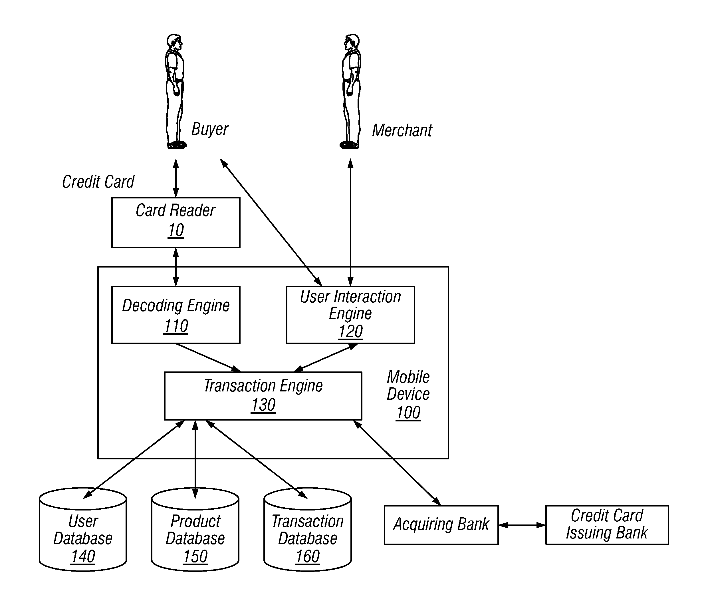
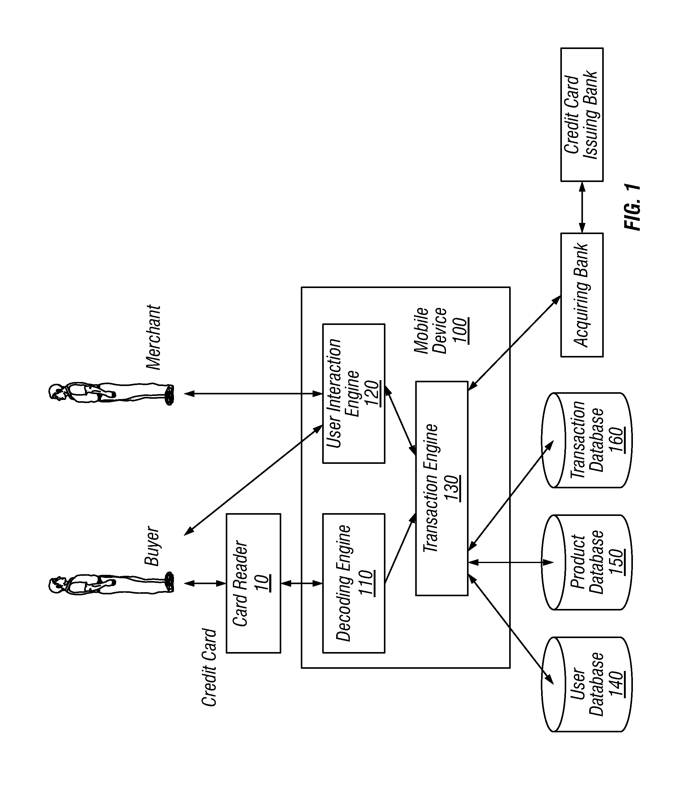
[0065]FIG. 1 depicts an example of a system diagram to support financial transaction between a payer and a payee through a miniaturized card reader connected to a mobile device. Although the diagrams depict components as functionally separate, such depiction is merely for illustrative purposes. It will be apparent that the components portrayed in this figure can be arbitrarily combined or divided into separate software, firmware and / or hardware components. Furthermore, it will also be apparent that such components, regardless of how they are combined or divided, can execute on the same host or multiple hosts, and wherein multiple hosts...


PUM


Abstract

A method of reconstructing a packet that includes financial card information from a mobile device uses a card reader. The card reader has a read head, a slot for swiping a magnetic stripe of a card and device electronics that includes a microcontroller with logic resources with code. The card reader has a unique identifier and associated cryptographic key. The same code is used to produce an encrypted and signed signal. The encrypted and signed signal, that includes the card reader identifier, is sent to the mobile device. The mobile device sends an encrypted and signed packet to a back end of a payment system. A cryptographic key is sued to decrypt and verify the contents of the packet at the back end. Non-encrypted financial card information is sent to a payment gateway.

Description

CROSS-REFERENCE TO RELATED APPLICATIONS[0001]This application is a continuation-in-part of U.S. Ser. No. 13 / 192,147 filed Jul. 27, 2011, which application is a divisional of U.S. Ser. No. 13 / 179,836, filed Jul. 11, 2011, which application is a continuation-in-part of U.S. Ser. No. 12 / 707,228, which is a continuation of U.S. Ser. No. 12 / 050,752 filed Mar. 18, 2008, which is a continuation of U.S. Ser. No. 10 / 355,557 filed Jan. 31, 2003, which claims the benefit of U.S. 60 / 355,667 filed Feb. 5, 2002, U.S. 60,356,861 filed Feb. 12, 2002, and U.S. 60,361,646 filed Mar. 4, 2002. Said Ser. No. 12 / 707,228 is also a continuation-in-part of U.S. Ser. No. 12 / 903,753, U.S. Ser. No. 12 / 903,823, both filed Oct. 13, 2010, U.S. Ser. No. 12 / 985,822 and U.S. Ser. No. 12 / 895,982, both filed January, 2011, U.S. Ser. No. 13 / 010,796, filed Jan. 21, 2011 and U.S. Ser. No. 13 / 012,495, filed Jan. 24, 2011.[0002]This application is related to U.S. Ser. No. 12 / 456,134, filed Jun. 10, 2009, and is hereby inco...

Claims


Application Information

Patent Timeline
IPC IPC(8): G06Q20/40
CPCG06Q20/322G06Q20/347G07F7/0886G06Q30/06G06Q40/02G06Q20/3829G06F21/6209
Inventor DORSEY, JACKMCCAULEY, NATHAN P.CUMMINS, JUSTIN PHILLIPMONICA, DIOGOQUIGLEY, OLIVER SAMUEL CURRANMCKELVEY, JAMES M.
Owner BLOCK INC
Learn More