
Multipath switching over multiple storage systems

a storage system and multi-path technology, applied in the field of multi-path storage systems, can solve the problems of i/o service interruption through data migration beyond storage systems, mission critical applications or business critical applications running at enterprise datacenters cannot be suspended while keeping their business stability, and i/o service interruption afterward

Active Publication Date: 2012-05-24
HITACHI LTD
View PDF3 Cites 104 Cited by
  • Summary
  • Abstract
  • Description
  • Claims
  • Application Information

AI Technical Summary

Benefits of technology

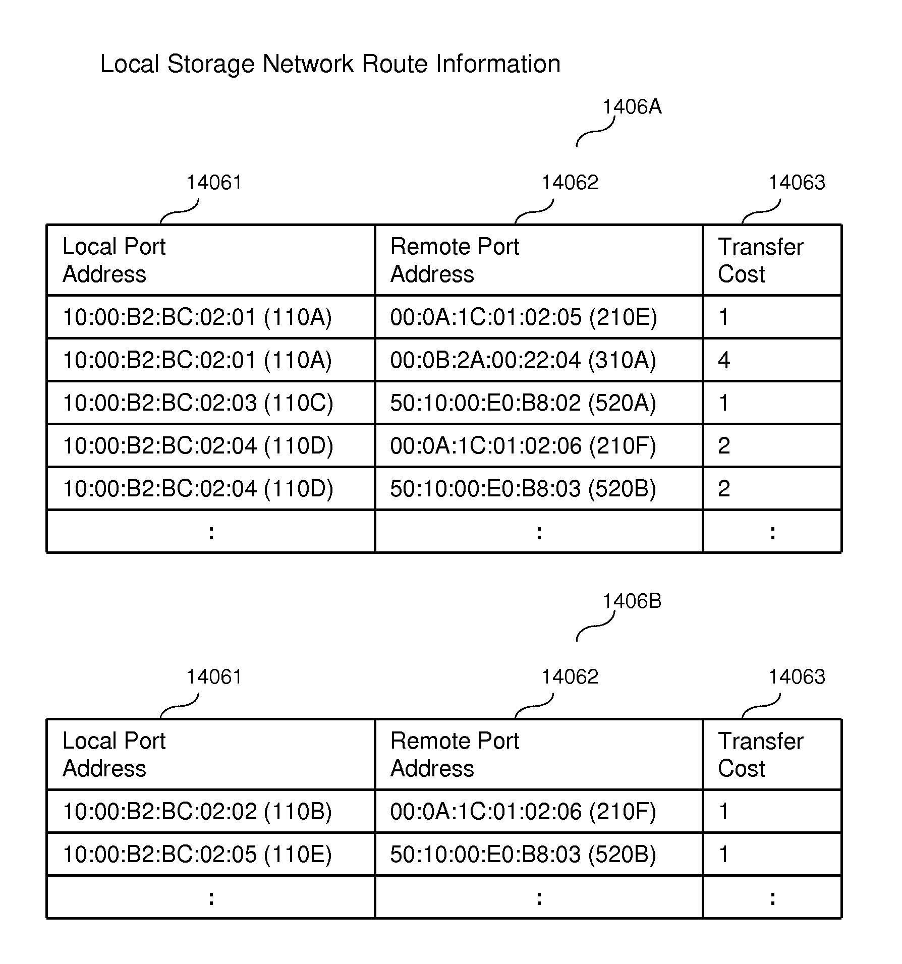
[0006]Exemplary embodiments of the invention provide nondisruptive data migration and I / O load balancing over multipath connections by running a virtual switch across storage systems and multipathing among storage and server. The data storage is equipped with switching functionality and virtual port (network interface). Network routing and path configuration setting are shared among multiple data storage systems. Logically, a single virtual network switch runs across multiple data storage systems. Network devices have the capability to establish multipath communication between server and storage. This allows I / O service continuation after removal of old data storage device, because another data path keeps communication alive with the migration target device. In this way, the invention allows running a virtual switch across storage systems and multipathing among storage and server, so as to complete non-disruptive data migration and I / O load balancing over multipath connections.

Problems solved by technology

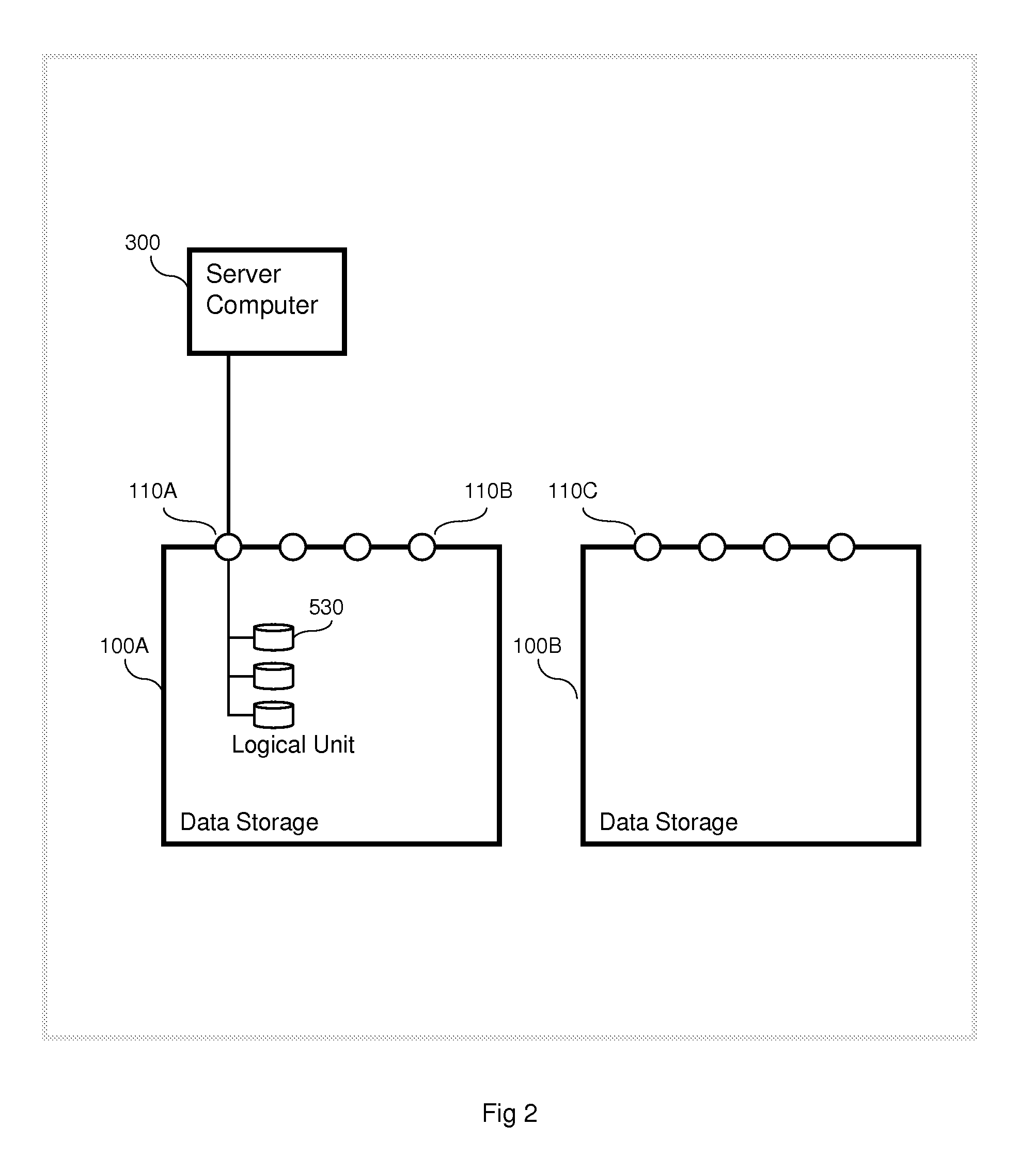
In addition to L2 networking, another problem is that I / O service interruption happens through data migration beyond storage systems. FIG. 2 is an example of a conventional logical configuration of a storage area network.
However, a mission critical application or a business critical application running at an Enterprise Datacenter cannot be suspended while keeping its business stability.
Furthermore, an additional problem of traditional single path network is that I / O service could be interrupted after the removal of the storage system 100A because the network path must be reset onto the new data storage device.

Method used


Image

  • Multipath switching over multiple storage systems
  • Multipath switching over multiple storage systems
  • Multipath switching over multiple storage systems

Examples


Embodiment Construction

[0039]In the following detailed description of the invention, reference is made to the accompanying drawings which form a part of the disclosure, and in which are shown by way of illustration, and not of limitation, exemplary embodiments by which the invention may be practiced. In the drawings, like numerals describe substantially similar components throughout the several views. Further, it should be noted that while the detailed description provides various exemplary embodiments, as described below and as illustrated in the drawings, the present invention is not limited to the embodiments described and illustrated herein, but can extend to other embodiments, as would be known or as would become known to those skilled in the art. Reference in the specification to “one embodiment,”“this embodiment,” or “these embodiments” means that a particular feature, structure, or characteristic described in connection with the embodiment is included in at least one embodiment of the invention, a...


PUM


Abstract

A system comprises a first storage system, a second storage system, a plurality of switches, and a server connected with the first storage system via a first group of switches and connected with the second storage system via a second group of switches. The first group and the second group have at least one switch which is not included in both the first and second groups. The first storage system receives I / O commands targeted to first logical units from the server via the first group of switches. The first storage system maintains first information regarding the ports of both the first and second storage systems. The first information is used to generate multipath communication between the server and the first storage system, including at least one path which passes through the second storage system and at least one other path which does not pass through the second storage system.

Description

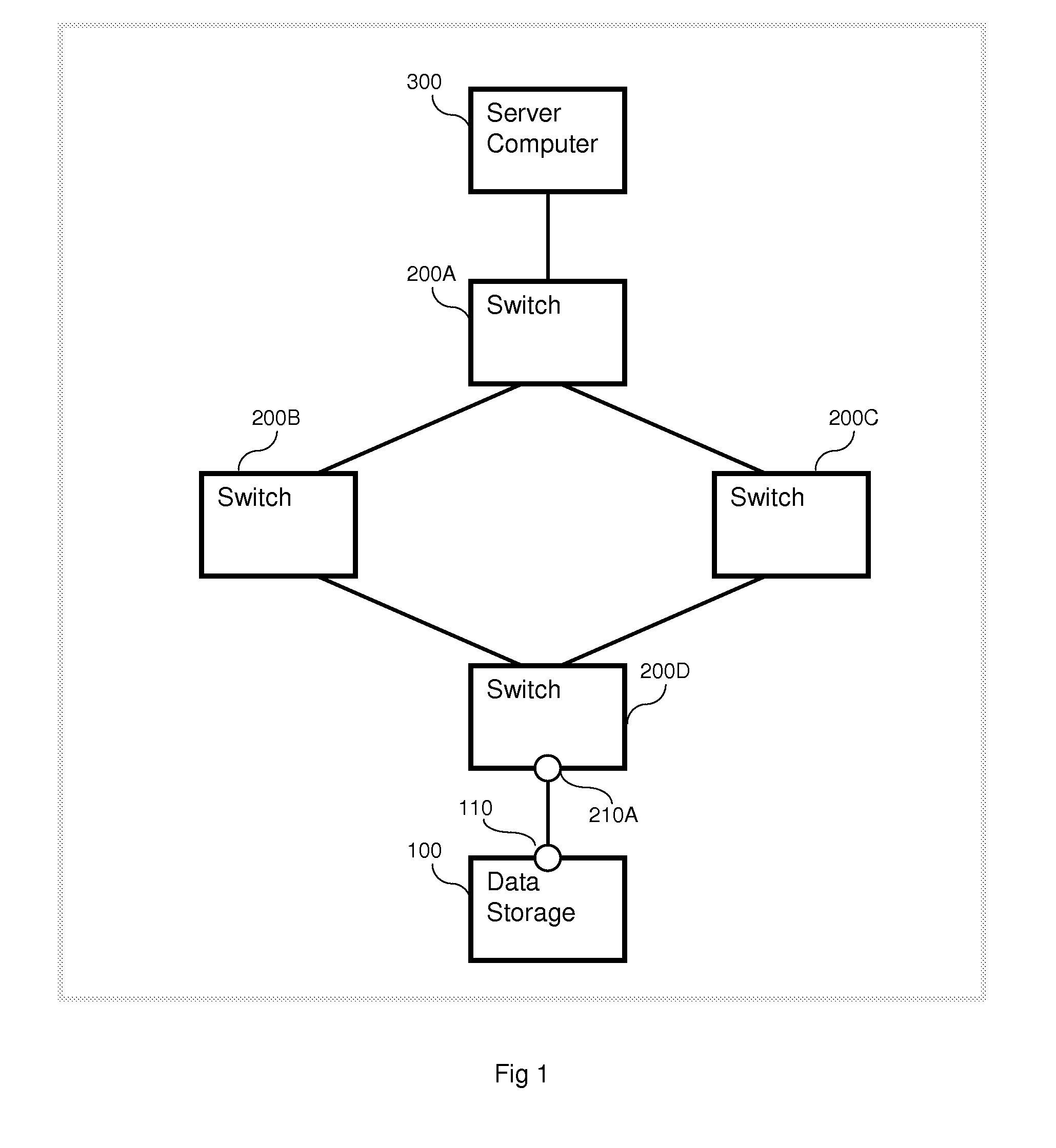
BACKGROUND OF THE INVENTION[0001]The present invention relates generally to multipath storage systems and, more particularly, to nondisruptive data migration and I / O load balancing over multipath connections by running a virtual switch across storage systems and multipathing among storage and server.[0002]According to recent trends, a new multipath networking method known as TRILL (Transparent Interconnection of Lots of Links) is under standardization process for networking over Layer 2 (L2) Ethernet. TRILL allows L2 network to establish two parallel data transfer paths that have not been allowed in traditional Ethernet based on STP (Spanning Tree Protocol). When TRILL is set up and ready in a storage network, data transfer between server and storage will be performed through multiple paths.[0003]FIG. 1 is an example of a conventional storage area network topology. A server computer 300 is coupled to a switch 200A, which is coupled to switches 200B and 200C in parallel, which are co...

Claims


Application Information

Patent Timeline
IPC IPC(8): G06F12/16G06F12/00G06F15/167
CPCG06F3/0607G06F3/0617G06F3/0635G06F3/0647H04L45/586G06F2206/1012H04L45/122H04L45/24G06F3/067
Inventor TAGUCHI, YUICHIHAGA, FUTOSHIOTANI, TOSHIO
Owner HITACHI LTD
Learn More