Pneumatic tire

Active Publication Date: 2012-05-31
THE GOODYEAR TIRE & RUBBER CO
View PDF11 Cites 28 Cited by
  • Summary
  • Abstract
  • Description
  • Claims
  • Application Information

AI Technical Summary

Benefits of technology

[0007]Thus, it is an object of the invention to provide a tire with still better controllable or adj

Problems solved by technology

However, this can negatively influence the dynamic properties of the tire, particularly when different layers of rubber material are used in each tread block for adjusting the properties of the tread.
According to the prior art, the radially lowest

Method used


Image

  • Pneumatic tire
  • Pneumatic tire
  • Pneumatic tire

Examples


Embodiment Construction

[0025]The following language is of the best presently contemplated mode or modes of carrying out the invention. This description is made for the purpose of illustrating the general principles of the invention and should not be understood in a limiting sense. The scope of the invention is best determined by reference to the appended claims. The reference numerals as depicted in the drawings are the same as those referred to in the specification.

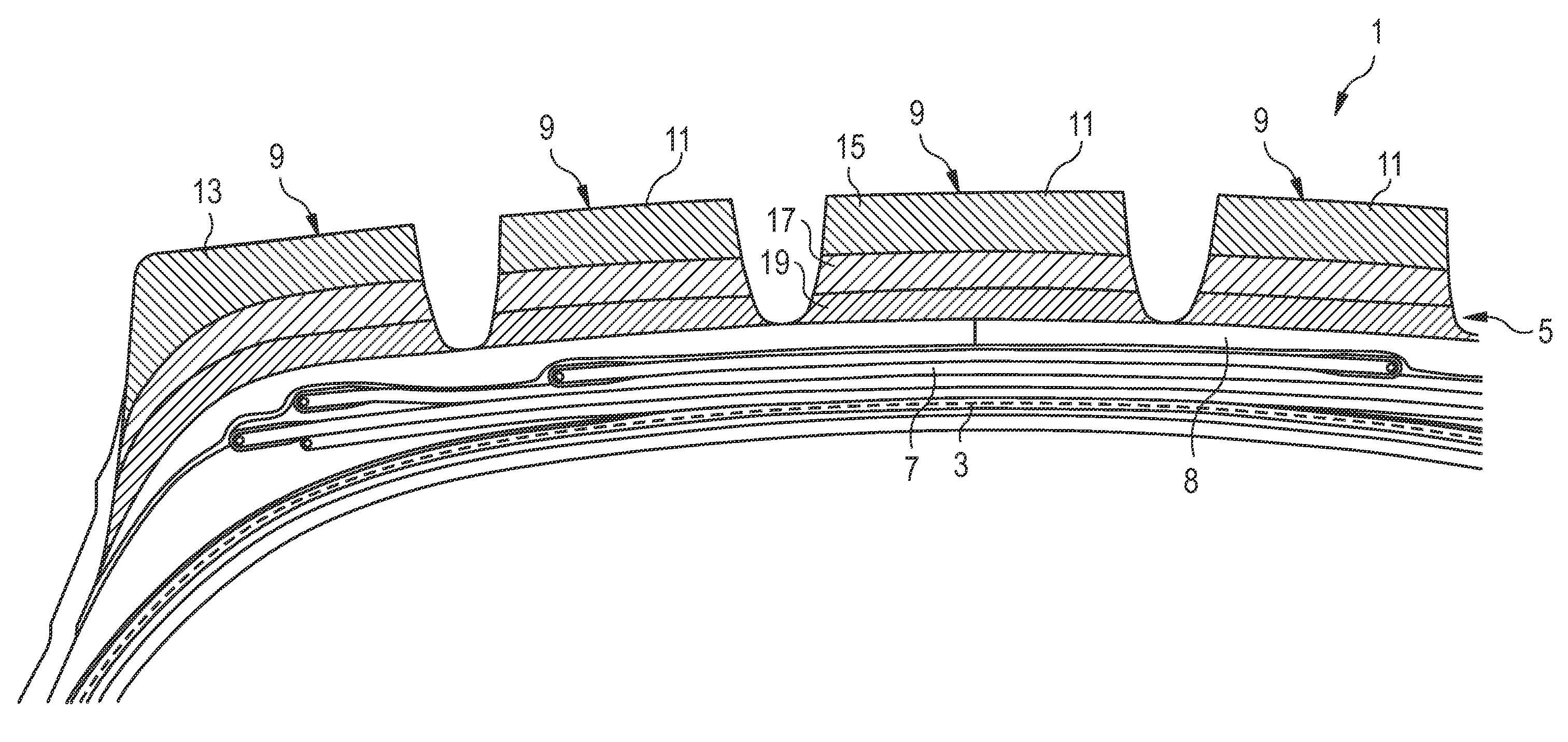
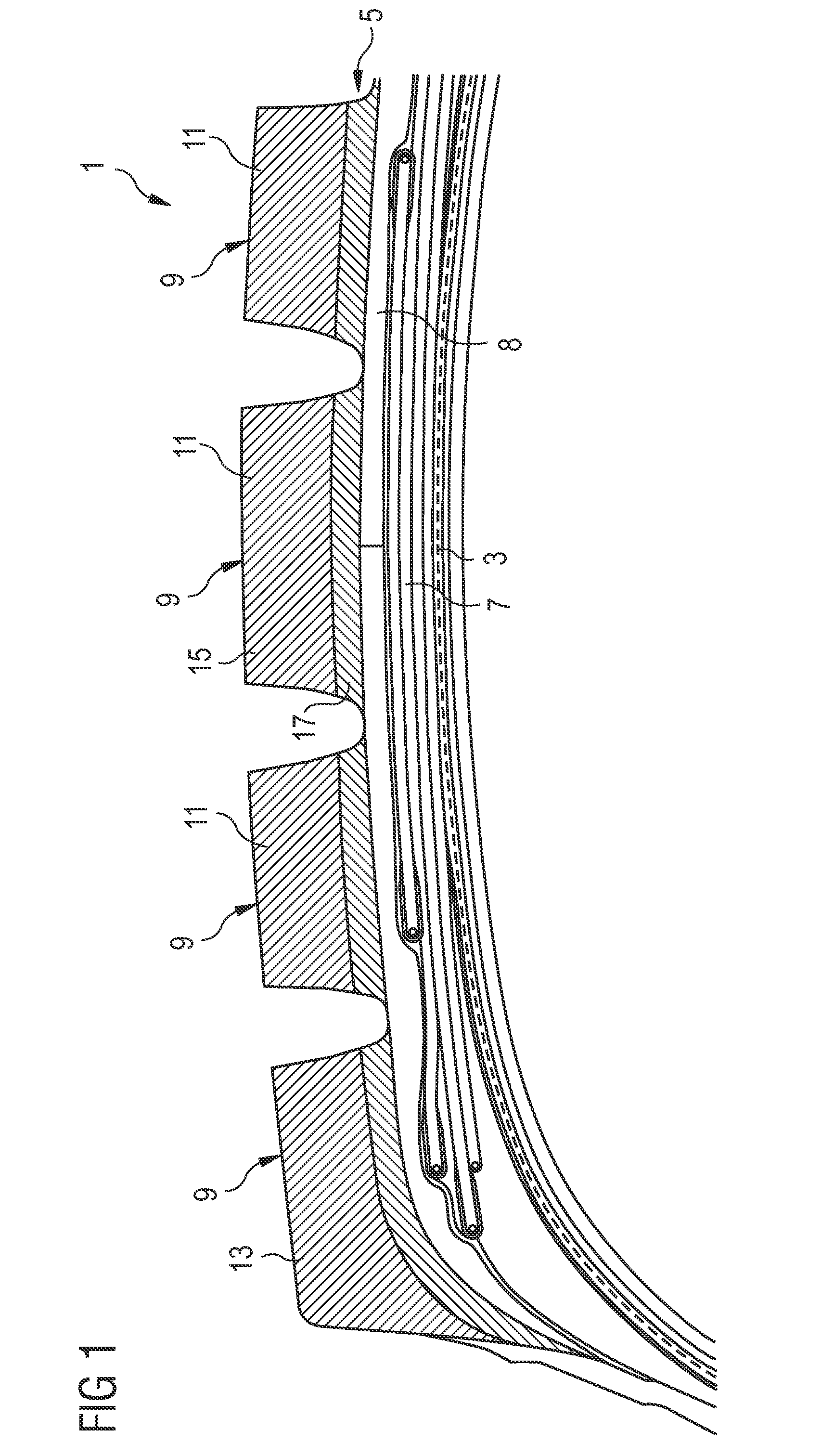
[0026]FIG. 1 shows a cross-sectional view of a part of a tire's crown in accordance with the invention. The depicted tire 1 comprises a carcass ply 3, a tread 5, and a belt portion 7. The tread 5 comprises multiple parts, i.e. the tread base layer 8 and further rubber layers 15, 17 in the tread blocks 9 of the tread 5. For the sake of a better characterization it is distinguished between center tread blocks 11 and shoulder tread blocks 13. Shoulder blocks 13 are the axially outermost tread blocks in the shoulder area of the tire 1. The amount,...


PUM


Abstract

The present invention is directed to a pneumatic tire 1 comprising at least one pair of parallel annular beads; at least one carcass ply 3 wrapped around said beads; a tread 5; and first and second sidewalls disposed between said tread and one of said at least one pair of beads; as well as a belt portion 7 between the carcass ply 3 and the tread 5. In accordance with the invention, the tread 5 comprises a tread base layer 8 and a plurality of tread blocks 9, wherein the tread blocks 9 comprise at least two different rubber layers 15, 17, 19 arranged radially above each other, whereas the rubber layers 15, 17, 19 of different tread blocks are axially separate from each other.

Description

FIELD OF THE INVENTION[0001]The present patent application is directed to a pneumatic tire comprising a multi-layer tread cap.BACKGROUND OF THE INVENTION[0002]In normal production of pneumatic tires, the extruded tread consists of only two compound parts, i.e. the cap and the base compound. Sometimes a calendared cushion is put on the base compound to avoid tack problems in tire building.[0003]EP 1 398 182 A2 discloses a tire having a multi-layered tread. In detail, the respective tire comprises a tread base layer, an intermediate layer, and a cap layer comprising lugs and grooves. The tread cap layer comes into contact with the road, wherein the intermediate layer extends to and includes a visible bottom portion of said grooves in said cap layer. Furthermore, said intermediate layer is comprised of a carbon black-rich rubber compound. However, the intermediate layer is not intended to contact the street upon normal wear of the tire.[0004]Document U.S. Pat. No. 5,176,765 discloses a...

Claims


Application Information

Patent Timeline
IPC IPC(8): B60C11/11
CPCB60C2200/06B60C11/0058B60C11/005B60C2011/0025
Inventor COLLETTE, JACQUESMAUS, PETER JOHANN CORNELIUS
Owner THE GOODYEAR TIRE & RUBBER CO
Why Eureka
Try Eureka