

Illumination device and video projector
a technology of projection device and projection device, which is applied in the direction of picture reproducers using projection device, television systems, lighting and heating apparatus, etc., can solve the problem of difficulty in a video projector to meet such different demands
- Summary
- Abstract
- Description
- Claims
- Application Information
AI Technical Summary
Benefits of technology
Problems solved by technology
Method used
Image

Examples
first embodiment
[0029]An illumination device 1 according to a first embodiment of the present invention will now be described with reference to FIGS. 1 to 4.
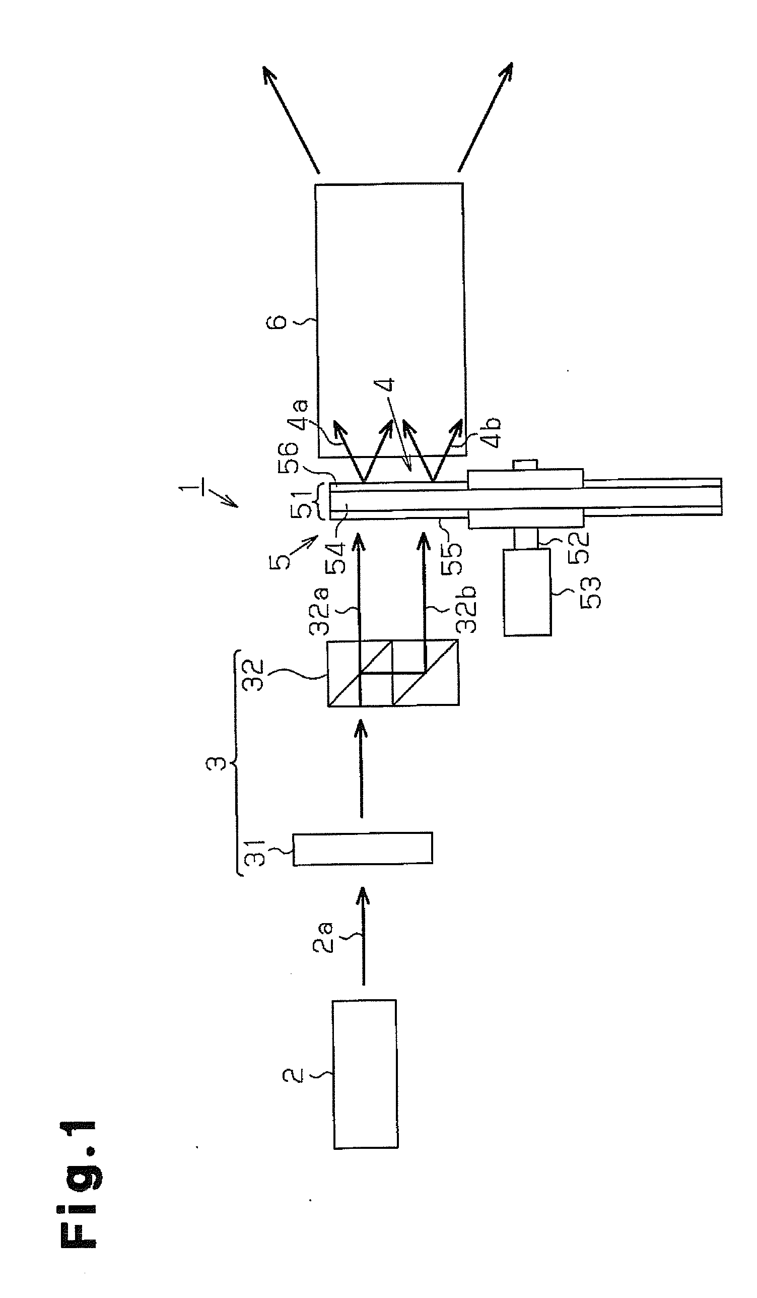
[0030]Referring to FIG. 1, the illumination device 1 includes a light source 2, a light splitting unit 3, a light conversion unit 4, a switching unit 5, and a combining unit 6. The light splitting unit 3 splits polarized light emitted from the light source 2 at a given ratio. The light conversion unit 4 includes light converters that convert two beams of polarized light emitted from the light splitting unit 3 into colored light. The switching unit 5 sequentially switches the light converters of the light conversion unit 4. The combining unit 6 combines the beams of colored light sequentially emitted from the switching unit 5 and evens the brightness of the combined light.
[0031]The light source 2 may be formed by a semiconductor laser that emits ultraviolet rays forming polarized light 2a polarized in a single direction. The light source 2 may a...
second embodiment
[0059]A second embodiment will now be described with reference to FIG. 5.
[0060]In the second embodiment, a video projector uses the illumination device of the first embodiment. To avoid redundancy, like or same reference numerals are given to those components that are the same as the corresponding components of the first embodiment. Such components will now be described.
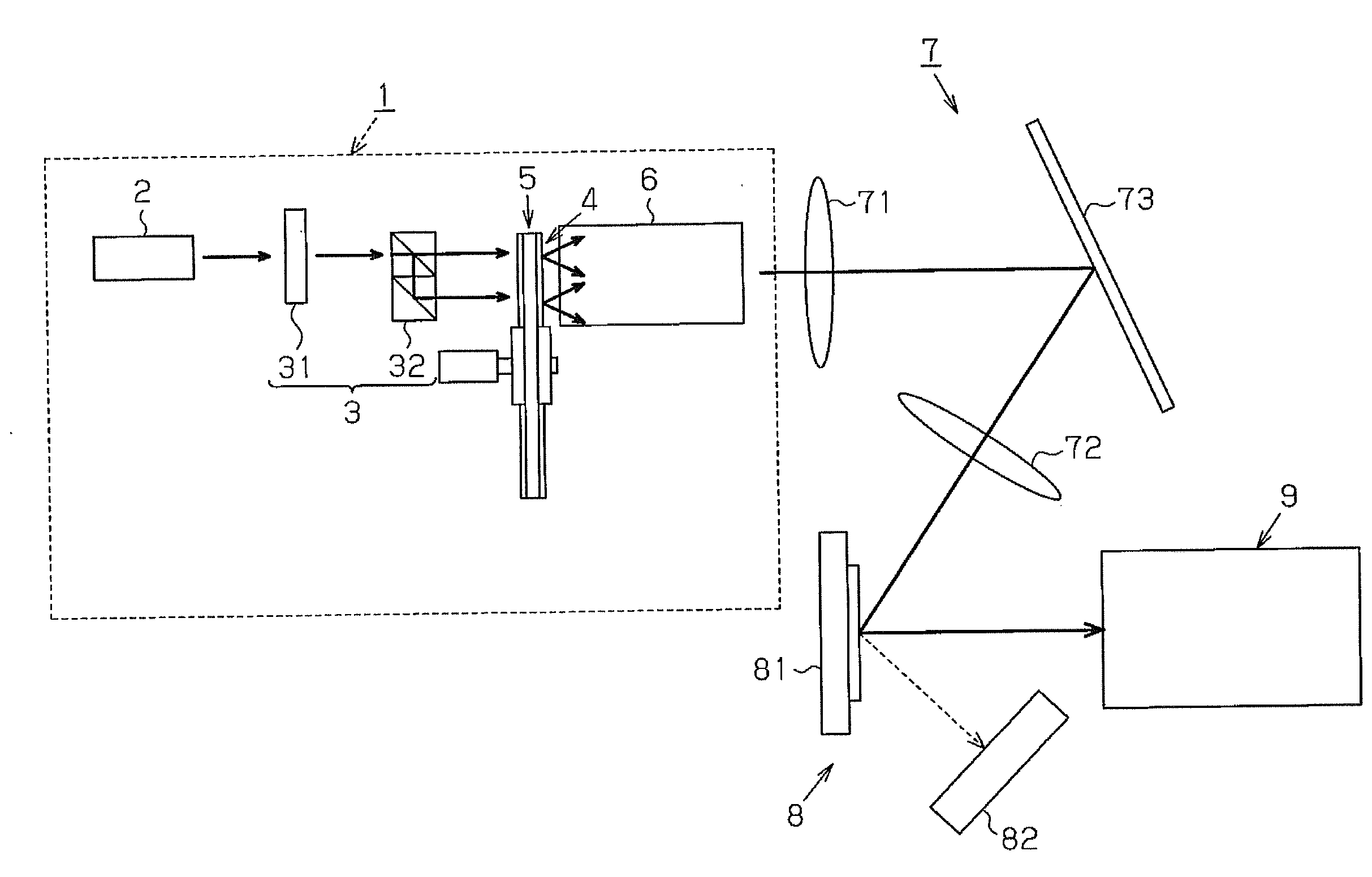
[0061]In the present embodiment, the video projector includes the illumination device 1 of the first embodiment, a guide optical system 7, a modulation device 8, and a projection lens 9. The guide optical system 7 guides colored light emitted from the illumination device 1 to the modulation device 8. The modulation device 8 optically modulates the colored light based on the image signal. The projection lens 9 enlarges and projects image light, which is modulated by the modulation device 8.
[0062]The guide optical system 7 includes condenser lenses 71 and 72 and a full reflection lens 73. Further, the guide optical sys...
third embodiment
[0072]An illumination device of the third embodiment differs from the illumination device 1 of the first embodiment in that the polarized light 2a emitted from a light source is split into three by a given ratio. The illumination device of the present embodiment will now be described with reference to FIGS. 6 and 7. To avoid redundancy, like or same reference numerals are given to those components that are the same as the corresponding components of the first embodiment. Such components will not be described.
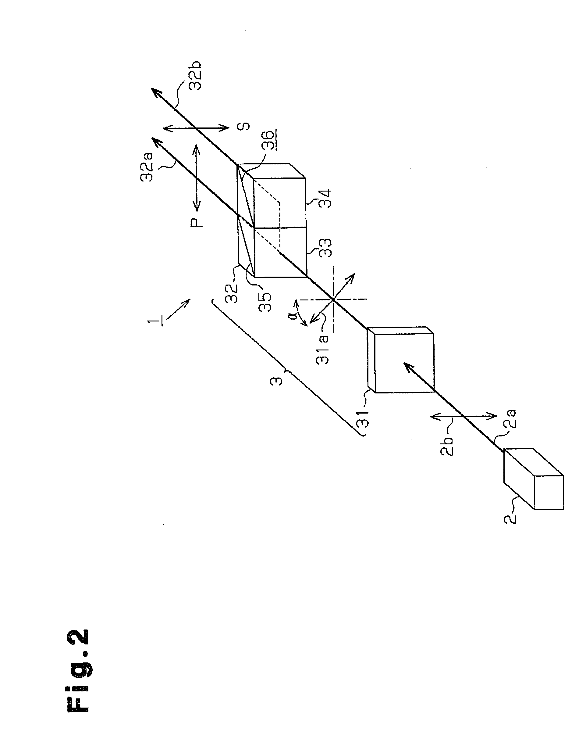
[0073]Referring to FIG. 6, in the same manner as the first embodiment, the light splitting unit 3 includes a polarization rotation element 31 and the polarization beam splitter 32. The polarization rotation element 31 rotates the polarized light 2a emitted from the light source 2 in a single direction to a given polarization direction. The polarized light of which polarization direction has been changed by the polarization rotation element 31 is split into two by the polarizatio...
PUM
 Abstract
Description
Claims
Application Information