
Laser confocal sensor metrology system

Inactive Publication Date: 2012-05-31
JOHNSON & JOHNSON VISION CARE INC
View PDF3 Cites 18 Cited by
  • Summary
  • Abstract
  • Description
  • Claims
  • Application Information

AI Technical Summary

Benefits of technology

[0009]Accordingly, the present invention is directed to methods and apparatus for measuring an ophthalmic lens and in some embodiments, a non-contact optical instrument may be utilized to

Problems solved by technology

However, the nature of the injection molding processes and equipment make it difficult to form custom lenses specific to a particular patient's eye or a particular application.
However, lathing requires a high modulus lens material is time consuming and limited in the scope of the surface available and stereo lithography has not yielded a lens suitable for human use.

Method used


Image

  • Laser confocal sensor metrology system
  • Laser confocal sensor metrology system
  • Laser confocal sensor metrology system

Examples


Embodiment Construction

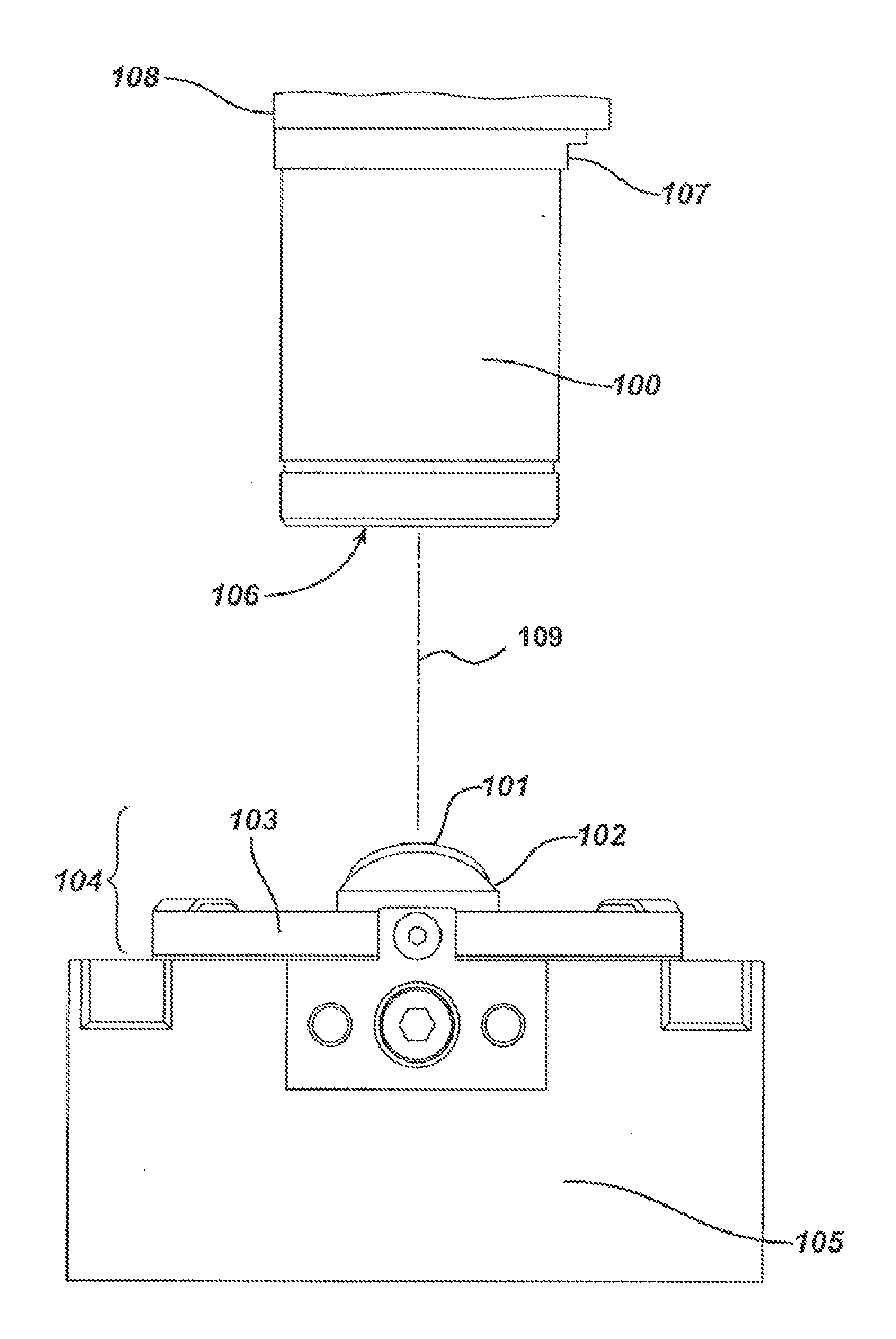
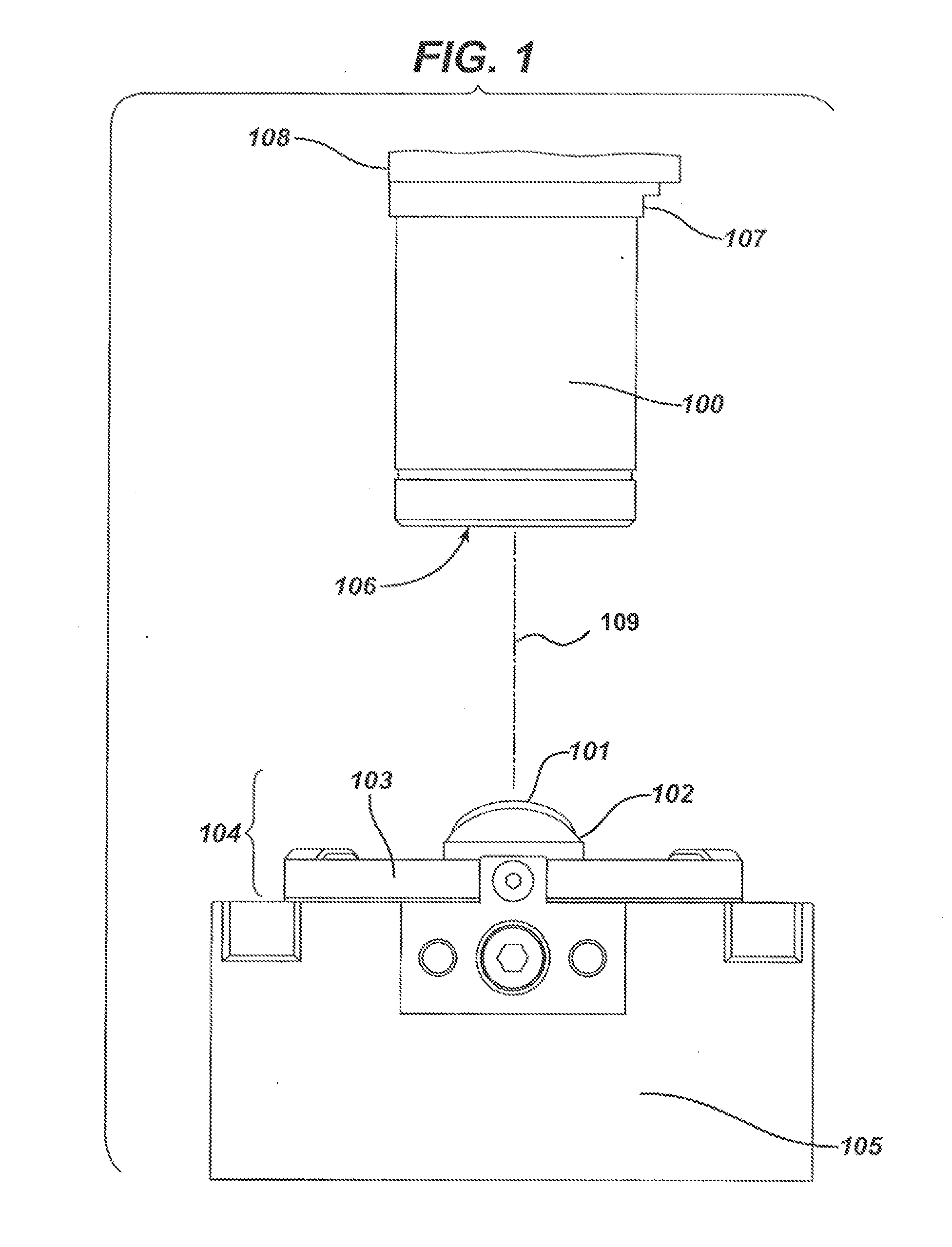
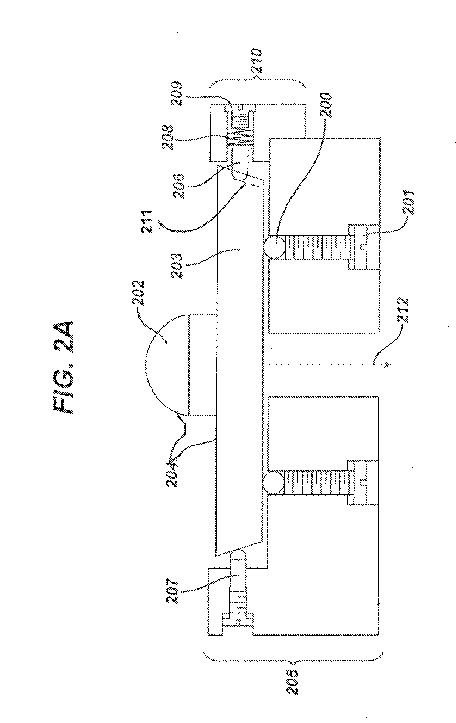
[0023]The present invention provides for methods and apparatus for measuring a thickness of one or both of a lens and Lens Precursor. In the following sections detailed descriptions of embodiments of the invention will be given. The description of both preferred and alternative embodiments though thorough are exemplary embodiments only, and it is understood to those skilled in the art that variations, modifications and alterations may be apparent. It is therefore to be understood that said exemplary embodiments do not limit the broadness of the aspects of the underlying invention. Method steps described herein are listed in a logical sequence in this discussion. However, this sequence in no way limits the order in which they may be implemented unless specifically stated. In addition, not all of the steps are required to implement the present invention and additional steps may be included in various embodiments of the present invention.

GLOSSARY

[0024]In this description and claims dir...


PUM


Abstract

The present invention provides apparatus for a non-contact method of obtaining accurate three-dimensional measurements of a dry contact lens, more specifically, using dry lens metrology to know the exact thickness of a contact lens.

Description

RELATED APPLICATIONS[0001]This application claims priority to U.S. Provisional Patent Application Ser. No. 61 / 418,148 which was filed on Nov. 30, 2010, the contents of which are relied upon and incorporated by reference.FIELD OF USE[0002]This invention describes apparatus for a non-contact method of obtaining accurate three-dimensional measurements of a dry contact lens, more specifically, using dry lens metrology to know the exact thickness of a contact lens.BACKGROUND OF THE INVENTION[0003]Ophthalmic lenses are often made by cast molding, in which a monomer material is deposited in a cavity defined between optical surfaces of opposing mold parts. Multi-part molds used to fashion hydrogels into a useful article, such as an ophthalmic lens, may include for example, a first mold part with a convex portion that corresponds with a back curve of an ophthalmic lens and a second mold part with a concave portion that corresponds with a front curve of the ophthalmic lens. To prepare a lens ...

Claims


Application Information

Patent Timeline
IPC IPC(8): G01B11/14
CPCG01B11/06G01B11/24G01M11/0207G01M11/02G01M11/0242G01M11/025G01M11/0214
Inventor WIDMAN, MICHAEL F.ENNS, JOHN B.POWELL, P. MARKSITES, PETER W.WILDSMITH, CHRISTOPHER
Owner JOHNSON & JOHNSON VISION CARE INC
Learn More