Area array sweep frequency measurement device and method

The technology of a measuring device and a measuring method, which is applied in the field of area array frequency sweep measuring devices, can solve problems such as inaccurate ranging

Pending Publication Date: 2021-04-27
武汉光目科技有限公司
View PDF0 Cites 0 Cited by
  • Summary
  • Abstract
  • Description
  • Claims
  • Application Information

AI Technical Summary

Problems solved by technology

It is designed to solve the problem of inaccurate ranging in the general field of view due to the er

Method used


Image

  • Area array sweep frequency measurement device and method
  • Area array sweep frequency measurement device and method
  • Area array sweep frequency measurement device and method

Examples


Embodiment 1

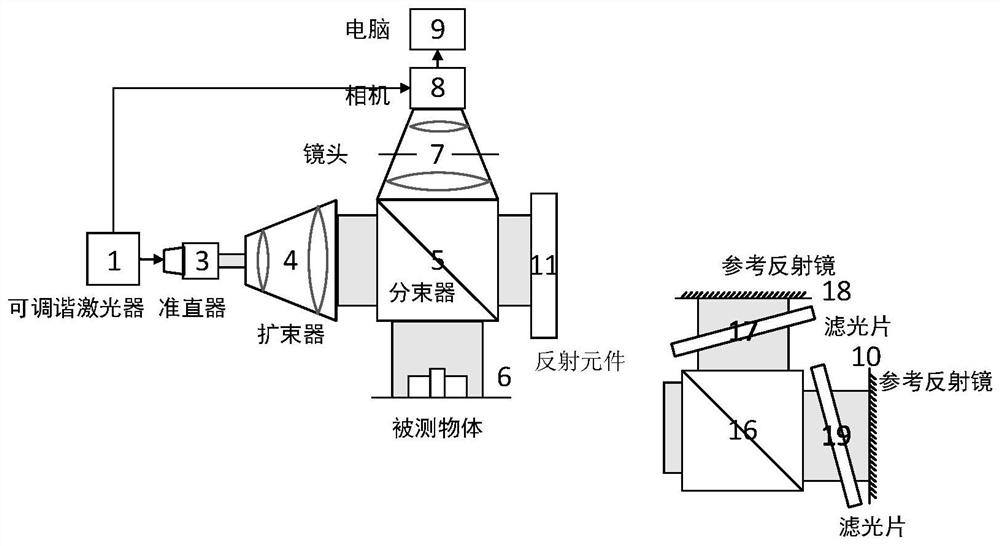
[0054] Such as figure 1 As shown, an area array frequency sweep measurement device is provided, including a tunable laser 1, a first collimator 3, a first beam expander 4, a first beam splitter 5, a lens 7, a reflective element 11, a camera 8 and computer 9;

[0055] A first beam splitter 5, a lens 7, a camera 8, and a computer 9 are arranged sequentially from bottom to top in the radial direction; a tunable laser 1 and a first collimator 3 are arranged sequentially from left to right in the transverse direction , the first beam expander 4, the first beam splitter 5 and the reflective element 11; the output end of the tunable laser 1 is connected to the input end of the camera 8;

[0056] The process of changing the wavelength of the output wavelength of the tunable laser 1 with time is called optical frequency scanning, referred to as frequency sweeping; A trigger signal, the trigger signal is used to control the camera 8 to start collecting; the computer 9 has signals for ...

Embodiment 2

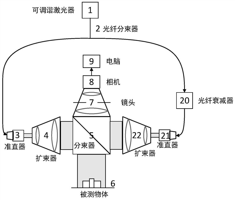
[0073] The refractive index of different measured objects may vary greatly. This embodiment adopts a general field of view optical path with a fiber optic beam splitter, which is convenient to use a fiber optic attenuator to adjust the light intensity of the reference arm without replacing the attenuator in the optical path, avoiding destroy the light path.

[0074] Such as figure 2 As shown, an area array frequency sweep measurement device is provided, including a tunable laser 1, a first collimator 3, a first beam expander 4, a first beam splitter 5, a lens 7, a camera 8, a computer 9, a first A fiber beam splitter 2, a second beam expander 22, a second collimator 21 and a fiber attenuator 20;

[0075] A first beam splitter 5, a lens 7, a camera 8, and a computer 9 are sequentially arranged from bottom to top in the radial direction; a first collimator 3, a first beam expander, 4, the first beam splitter 5, the second beam expander 22 and the second collimator 21; the out...

Embodiment 3

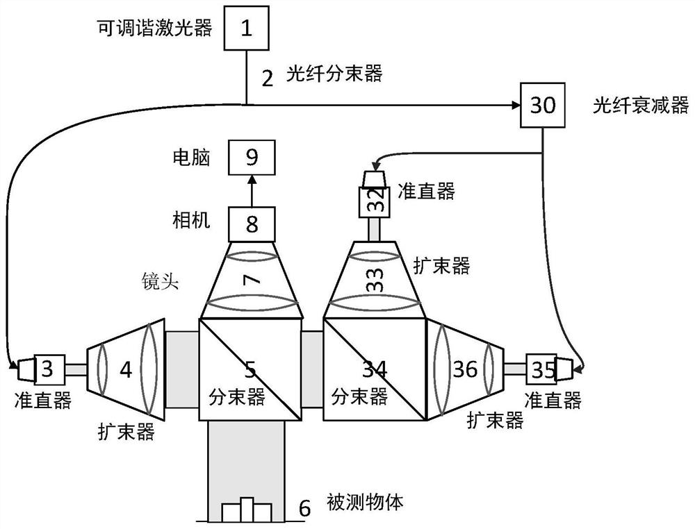
[0079] A general field of view optical path with a fiber optic beam splitter can use a dual reference arm structure to resolve distance ambiguity and dead zones. The principle is the same as that in Embodiment 1, except that the reference light in this embodiment is derived from transmitted light, and that in Embodiment 1 is derived from reflected light.

[0080] Such as image 3 As shown, an area array frequency sweep measurement device is provided, including a tunable laser 1, a first collimator 3, a first beam expander 4, a first beam splitter 5, a lens 7, a camera 8, a computer 9, a first An optical fiber beam splitter 2, a second optical fiber beam splitter 30, a fourth collimator 32, a third collimator 35, a third beam expander 36, a fourth beam expander 33, and a third beam splitter 34;

[0081] A first beam splitter 5, a lens 7, a camera 8, and a computer 9 are sequentially arranged from bottom to top in the radial direction; a first collimator 3, a first beam expander,...


PUM


Abstract

The invention provides an area array sweep frequency measurement device and method, and belongs to the technical field of laser ranging, and the device comprises a tunable laser, a first collimator, a first beam expander, a first beam splitter, a lens, a reflection element, a camera, and an acquisition control unit. The tunable laser is used for controlling the camera to acquire an interference image by sending a trigger signal and providing an original light beam; the first beam splitter is used for splitting the collimated and expanded light beam into a first light beam and a second light beam, and the first light beam irradiates a to-be-measured object and then is reflected; the reflection element is used for reflecting the second light beam to form reference light; and the camera is used for collecting an interference image formed by interference of the first reflected light and the reference light. According to the invention, a traditional point detection acquisition mode is replaced to acquire the surface topography, mechanical scanning errors introduced during point detection are avoided, and the measurement accuracy in a general field of view is improved.

Description

technical field [0001] The invention belongs to the technical field of laser distance measurement, and more specifically relates to an area array frequency sweep measurement device and method. Background technique [0002] In modern industrial production, the precision of parts processing has become more and more the key to high-performance equipment. It is very important to accurately and stably produce the required parts of specific size and shape. Therefore, accurate detection of the produced parts is an important link to ensure high-quality production. In the existing technology, it is often necessary to obtain the shape of the part through point-by-point scanning, and the measurement speed is limited by the scanning speed, so it is difficult to obtain high measurement speed with high sensitivity. This is determined by the characteristics of point scanning. Therefore, it is necessary to develop a large-scale, high-precision, and fast method for measuring the thickness ...

Claims


Application Information

Patent Timeline
IPC IPC(8): G01S17/08G01S7/481
CPCG01S7/481G01S17/08
Inventor 殷晓君于龙雷力谢谊李志标
Owner 武汉光目科技有限公司
Why Eureka
Try Eureka