Multifunction laser power meter

a laser power meter and multi-function technology, applied in the field of laser power measurement, can solve the problems of substantially more expensive beam profilers for users and power meters currently available, and cannot provide a measure of this beam siz

Active Publication Date: 2012-05-31
OPHIR OPTRONICS SOLUTIONS
View PDF5 Cites 30 Cited by
  • Summary
  • Abstract
  • Description
  • Claims
  • Application Information

AI Technical Summary

Benefits of technology

[0030](ii) a first thermopile having an effective diameter such that at least the majority of the region for absorbing the optical beam is contained within its effective diameter

Problems solved by technology

Power meters currently available are not able to provide a measure of this beam size.
Currently, a beam profiling instrument is generall

Method used


Image

  • Multifunction laser power meter
  • Multifunction laser power meter
  • Multifunction laser power meter

Examples


Embodiment Construction

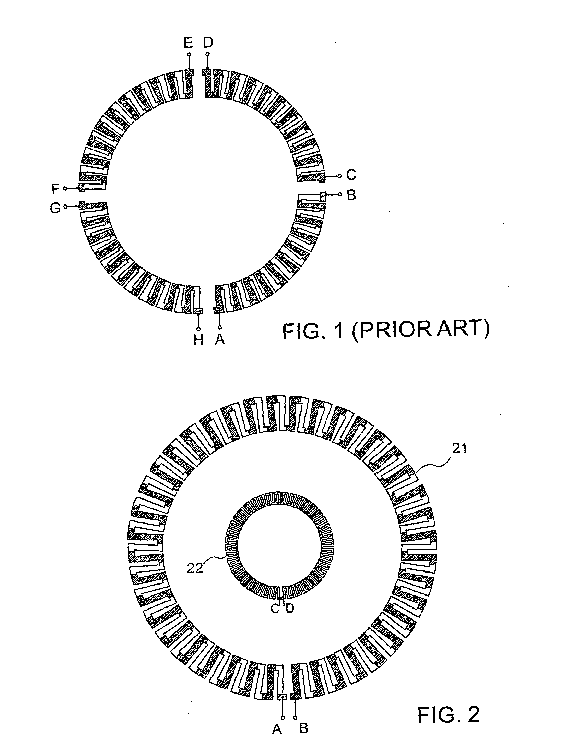
[0064]Reference is now made to FIG. 1, which illustrates schematically the four segmented thermopile pattern of a prior art laser power meter absorber disc. So long as the laser beam falls within the confines of the thermopile, its power will be integrated by the thermopile regardless of the beam size. The confines of the thermopile are generally defined by the effective diameter of the thermopile, which for most practical purposes can be taken as the diameter of the innermost junctions of the thermopile, these being the hot junctions. Comparison of the voltages from the four segments, AB, CD, EF and GH, provides beam position information.

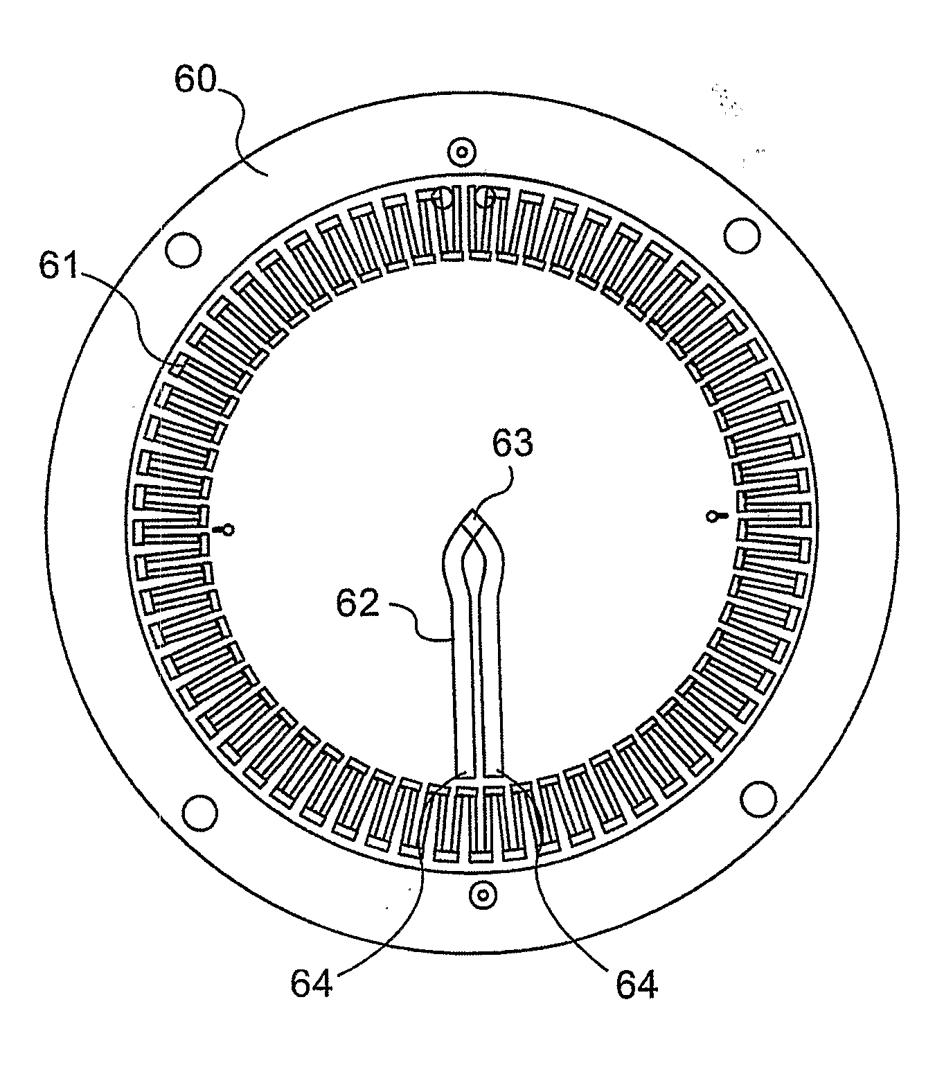
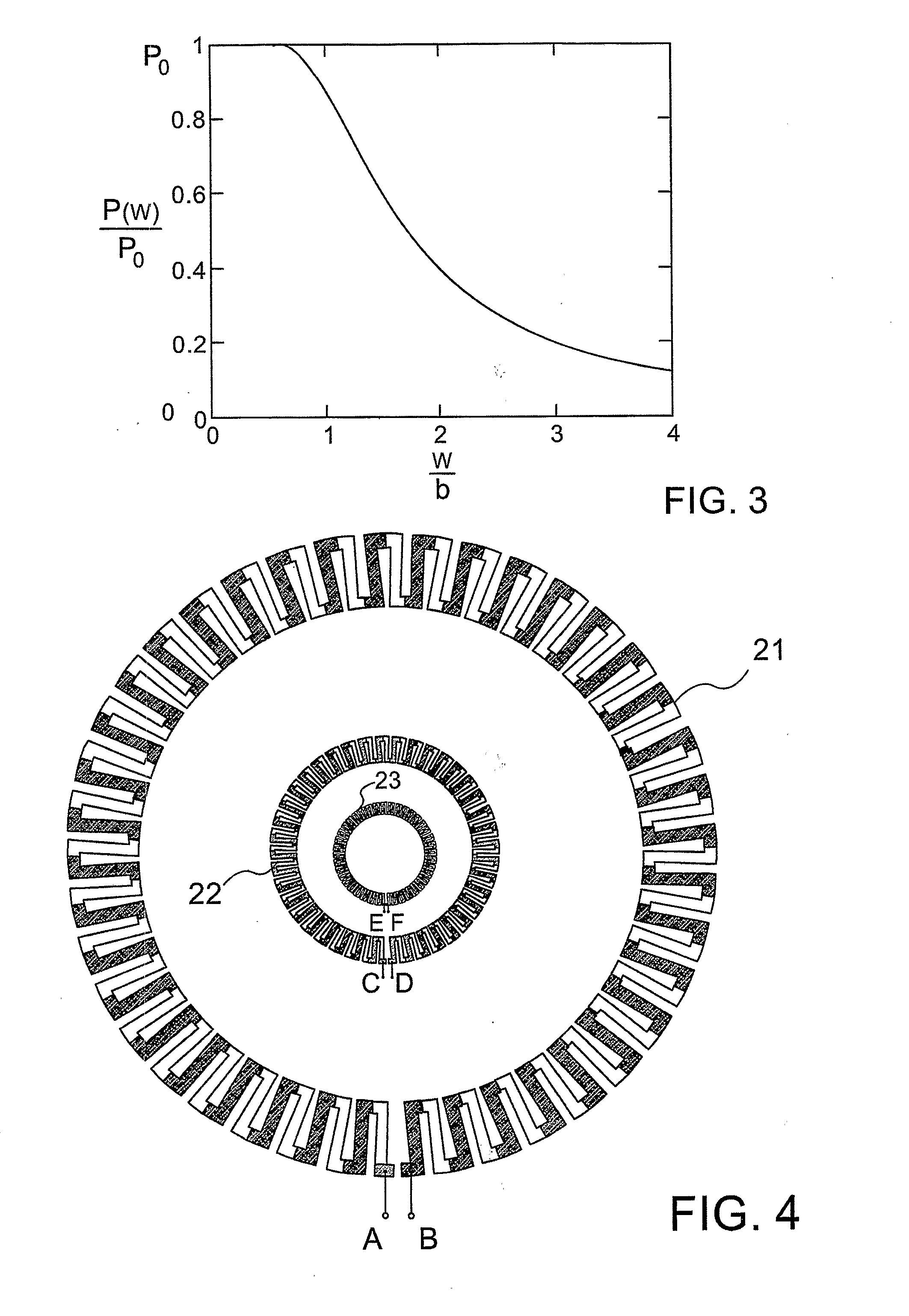
[0065]Reference is now made to FIG. 2 illustrates schematically the thermopile detector pattern of an exemplary laser power meter absorber disc according to a first exemplary embodiment. The disc has two sets of concentric thermopiles. The outer thermopile 21 is a segmented element, as is known in the prior art, though it could also be a single con...


PUM


Abstract

A laser power meter incorporating an absorber disc with a peripheral thermopile ring, either continuous or segmented, and an additional temperature detection element in the central portion, that enables measurement of beam size. This detection element can be a thermopile element, generally a ring of smaller diameter than the peripheral thermopile used, and located closer to the center of the absorber disc. With this arrangement the beam size can be measured, in addition to measurements of the power and the position of the beam. Alternatively, this centralized detection element can be a single thermocouple junction located at the center of the disc, which acts as the hot junction of a thermocouple pair. The second or cold junction is effectively located on the disc close to the peripheral thermopile. Alternatively, two temperature measuring elements can be used, one at the disc center and one at the periphery.

Description

FIELD OF THE INVENTION[0001]The present invention relates to the field of laser power measurements, and especially to power measurements which can also determine the size and position of the beam being measured.BACKGROUND OF THE INVENTION[0002]Optical power meters based on thermopile discs are well known in the art. Such discs are made of a heat conducting material, are heat-sinked at their periphery, and have a central absorber surface area on which the power to be measured impinges. A generally circular thermopile element is disposed near the outer edge of the disc surface, inward of the heat-sinked periphery, such that heat generated by the impinging beam flows outwards towards the cooled periphery, crosses the hot and cold junctions of the thermopile, and generates an integrated voltage across the ends of the thermopile proportional to the power falling on the absorber surface. An entrance aperture in the power meter head using such a disc limits the region of impingement of the...

Claims


Application Information

Patent Timeline
IPC IPC(8): G01K17/20
CPCG01K7/28G01K17/003G01J1/4257G01J5/12
Inventor BENDER, ELIYAHUELSTEIN, SHIMONIVKER, MARK
Owner OPHIR OPTRONICS SOLUTIONS
Why Eureka
Try Eureka