Mold clamping device for injection molding machine

A technology of injection molding machine and mold clamping device, applied in the field of mold clamping device, can solve problems such as unsatisfactory, rotational vibration, lubricant leakage, etc., and achieve the effect of high rigidity

Active Publication Date: 2009-12-02
SODICK CO LTD
View PDF1 Cites 5 Cited by
  • Summary
  • Abstract
  • Description
  • Claims
  • Application Information

AI Technical Summary

Problems solved by technology

Second, due to the complex structure in which the ball nut shaft is supported on the bearing cage and combined with the pulley through the connecting member
[0010] In addition, in the second configuration, since the rotational force driven by the timing belt is transmitted through a plurality of parts such as the pulley, the connecting member, the ball nut, and the bearing holder, the rigidity or machining accuracy (such as concentricity) of these parts is accumulated, As a result, unexpected rotational vibrations are prone to occur
[0011] In addition, in the third structure, there is a high possibility that the lubrication on the ball nut side is insufficient.
Generally, it is not ideal because the lubricating oil leaks out due to turning itself on the ball nut side

Method used


Image

  • Mold clamping device for injection molding machine
  • Mold clamping device for injection molding machine
  • Mold clamping device for injection molding machine

Examples


Embodiment Construction

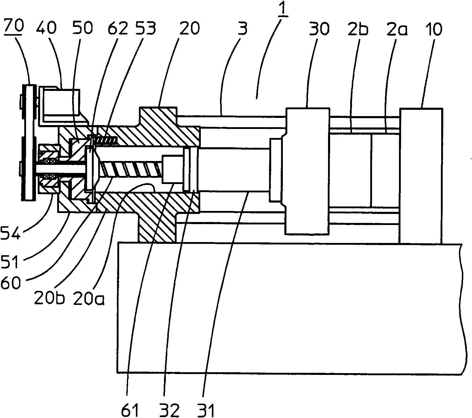
[0036] First, the outline of the mold clamping device will be described. Such as figure 1 As shown, the mold clamping device 1 has a fixed platen 10 on which a fixed-side metal mold 2a is installed, a reverse platen 20, and a movable platen 30 that moves while maintaining a state in which a movable metal mold 2b is installed; the fixed platen And reverse pressure plate is fastened by pull rod 3. In addition, the movable platen is opened and closed by an electric device such as a servo motor 40 , and the mold is clamped by a hydraulic device having a mold clamping head 50 . The elongation of the tie rod 3 by the mold clamping force is expressed as the movement distance of the counter platen 20 in the mold opening direction (hereinafter referred to as the rear) as described later as the mold clamping amount.

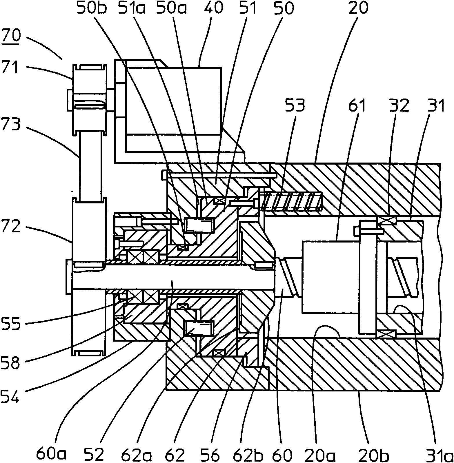
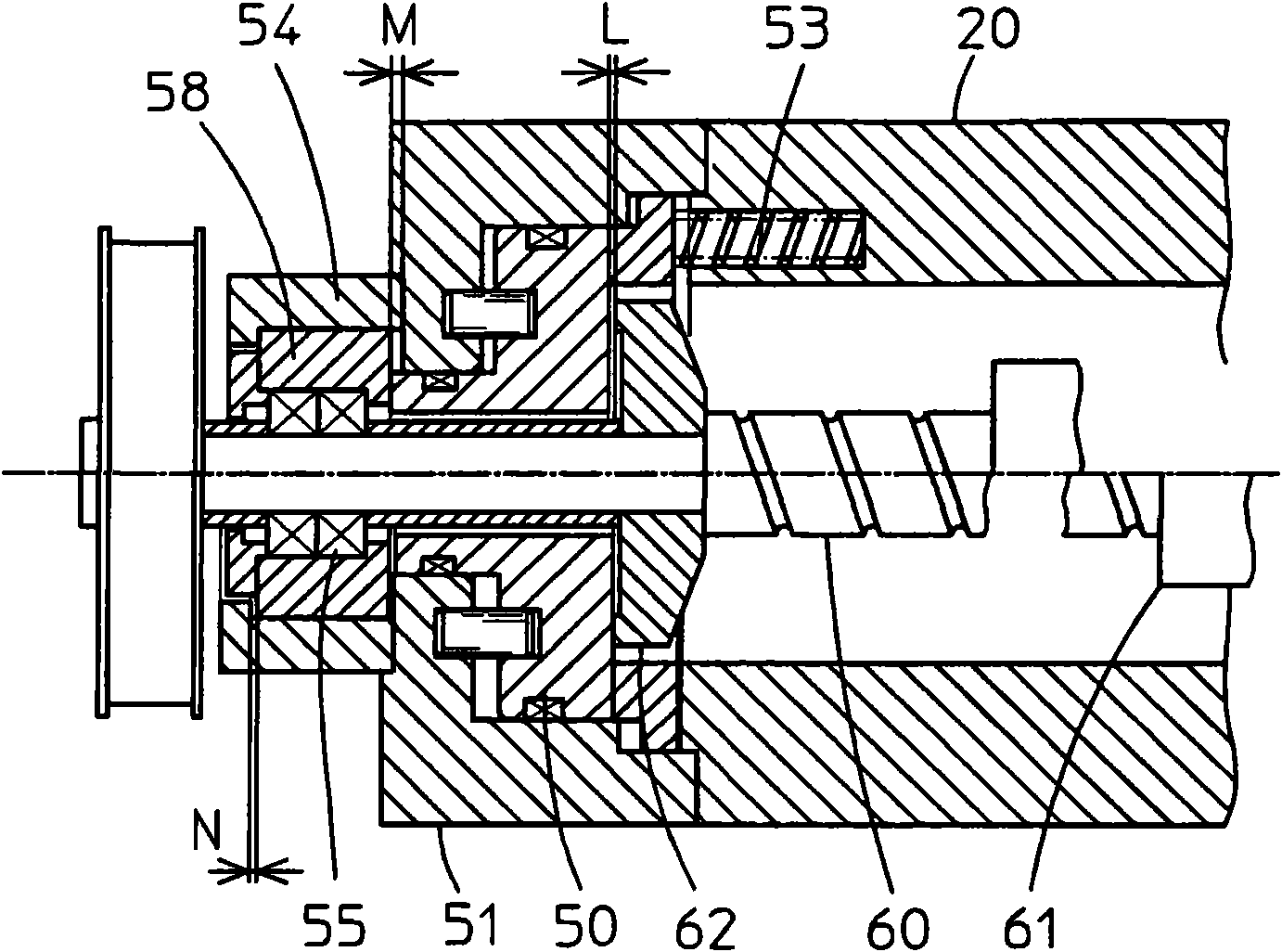
[0037] The present invention is a configuration adopted in such a hybrid mold clamping device, together with figure 2 Describe its main parts.

[0038] In the mold cl...


PUM


Abstract

A mold clamping device is provided for performing mold opening/closing by rotating a ball screw (60) fixed movably to a back platen (20) through a servo motor (40) and performing mold clamping by applying a mold clamping force to a flange-like member (62) integrated with the ball screw by a mold claming ram (50). A movable platen (30) has an operating shaft (31), with a ball nut (61) and a sliding bearing (32) at the distal end of the operation shaft. The flange-like member is arranged at a position against which the mold claming ram abuts only when it advances at the time of mold clamping. The mold claming ram is pressed in the mold opening direction by a push-in means (53). The mold clamping device slides the distal end of the operating shaft of the movable platen in its back platen under a state where the mold claming ram is spaced apart by a predetermined clearance L from the flange-like member when the mold is opened/closed, and presses the flange-like member by the mold claming ram.

Description

technical field [0001] The present invention relates to a mold clamping device of an injection molding machine in which the mold is opened and closed electrically by a servo motor and the mold is clamped hydraulically by a mold clamping head. Background technique [0002] The hybrid mold clamping device, which opens and closes the mold electrically and clamps the mold hydraulically, precisely controls the mold opening and closing movement while performing the mold clamping action with strong mold clamping force. Among such hybrid clamping devices, there are types that directly receive the clamping force on the ball screw and types that do not receive the clamping force. [0003] The present invention relates to the former mold clamping device which directly bears the mold clamping force on the ball screw. Among such mold clamping devices, there is, for example, the type proposed in Japanese Patent Publication No. 7-71807 (Patent Document 1). In this mold clamping device, a...

Claims


Application Information

Patent Timeline
Patent Type & Authority Applications(China)
IPC IPC(8): B29C33/22B29C45/68B22D17/26
CPCB29C45/68B22D17/26B29C2045/1792B29C33/22
Inventor 藤川操
Owner SODICK CO LTD
Why Eureka
Try Eureka