Connector and connector unit

a technology of connectors and units, applied in the direction of coupling parts, contact member manufacturing, coupling device connections, etc., can solve the problems of short life of insertion and removal between the coaxial connector b>500/b> and the coaxial adapter b>600/b>, and achieve the effect of improving the life of insertion and removal between the coaxial connector and the mating connector, reducing the size of the connector, and improving the diameter of the connector

Inactive Publication Date: 2012-05-31
JAPAN AVIATION ELECTRONICS IND LTD
View PDF4 Cites 13 Cited by
  • Summary
  • Abstract
  • Description
  • Claims
  • Application Information

AI Technical Summary

Benefits of technology

[0015]In this invention, by giving elasticity or springiness in terms of the shape to the shell body portion on its insertion opening side, when inserting the mating connector into the connector, the shell body portion is elastically deformed to increase its diameter on the insertion opening side and, therefore, the mating connecto

Problems solved by technology

However, the technique described in Patent Document 1 has a problem that the life of inse

Method used


Image

  • Connector and connector unit
  • Connector and connector unit
  • Connector and connector unit

Examples


Embodiment Construction

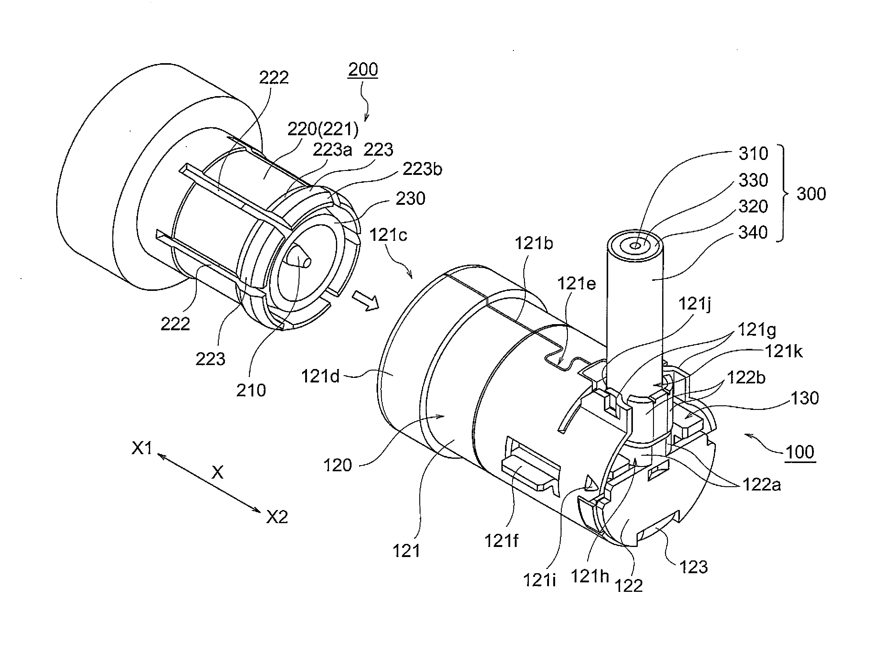
[0027]Hereinbelow, a connector unit according to an embodiment of this invention will be described with reference to the drawings.

[0028]In this embodiment, as shown in FIG. 1 etc., the connector unit comprises a connector 100 and a mating connector 200.

[0029]The connector 100 is a coaxial connector which is adapted to be attached to an end portion of a coaxial cable 300 for use in signal transmission, such as an antenna wire, thereby electrically connecting the coaxial cable 300 to the mating connector 200 inserted into the connector 100.

[0030]The connector 100 is formed as an MCX (micro coaxial) connector which is a snap-on / pull-off mating miniature connector.

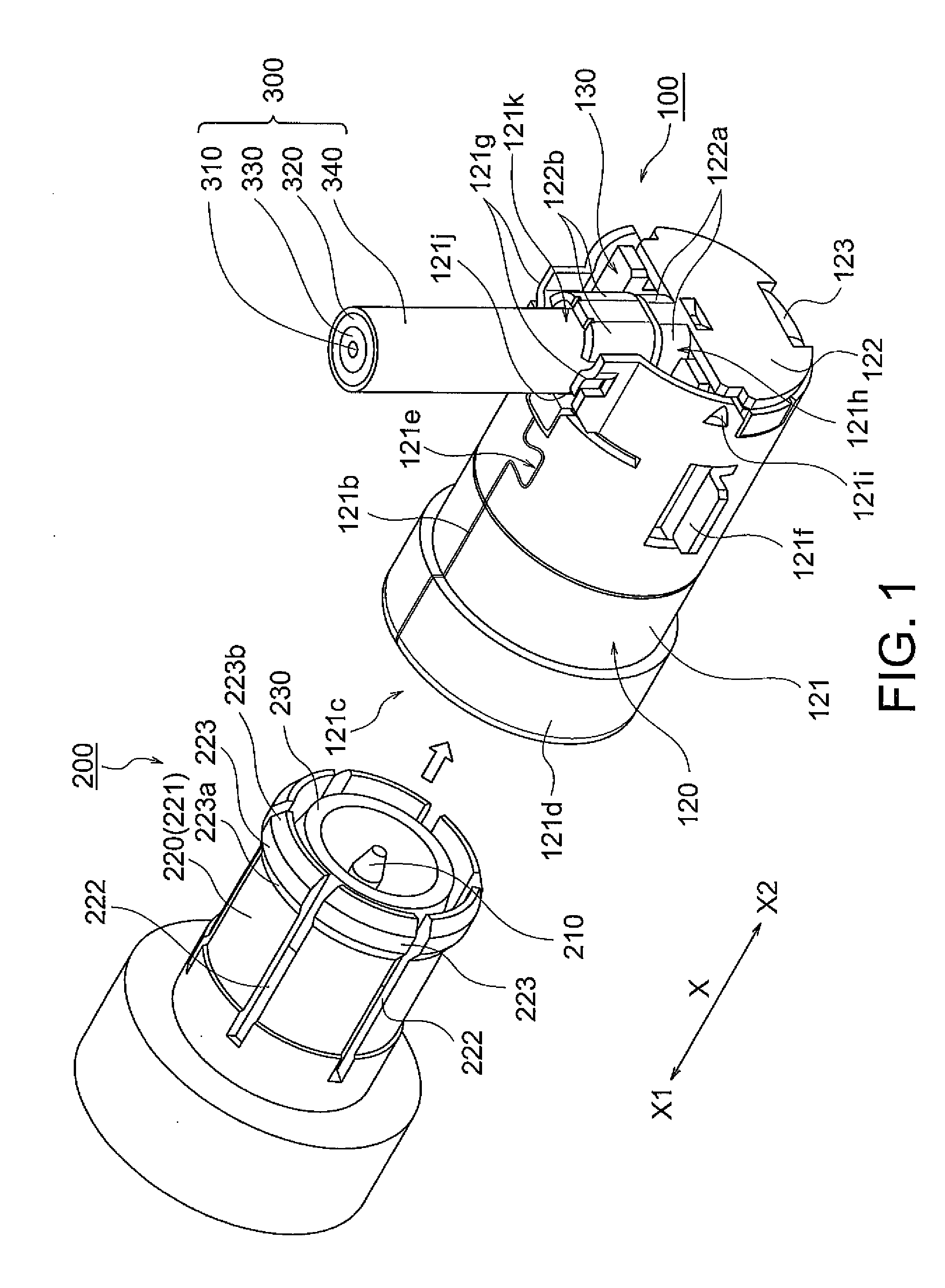
[0031]As shown in FIG. 9, the connector 100 is adapted to be mounted on a device D as a mounting object by means of a mounting member group E. The mounting member group E comprises a mounting member E1 and screws E2 and E3 for fixing the mounting member E1 to the device D.

[0032]As shown in FIGS. 1, 5, 7, etc., the connector 10...


PUM


Abstract

A connector includes a contact and a shell. The shell includes a tubular shell body portion having a slit portion formed to extend over its entire region in a connector insertion direction, an insertion opening formed at one end of the shell body portion, a locking portion provided on the inner periphery side of the shell body portion, and a shell joining portion formed at a position more on the forward side of the connector insertion direction than a position of the locking portion and joining together opposed portions of the shell body portion divided by the slit portion.

Description

[0001]This application is based upon and claims the benefit of priority from Japanese Patent Application No. 2010-262401, filed on Nov. 25, 2010, the disclosure of which is incorporated herein in its entirety by reference.TECHNICAL FIELD[0002]This invention relates to a connector and a connector unit and, in particular, relates to a coaxial connector and a coaxial connector unit.BACKGROUND ART[0003]Conventionally, as shown in FIG. 10, there is known a coaxial connector 500 comprising a center conductor 510 and a tubular housing 520 disposed around the center conductor 510 (see, e.g. JP-A-2007-323865 (Patent Document 1)). The housing 520 has an inner periphery formed with a convex portion 521m which is adapted to engage with convex portions 623 formed on an outer periphery of a tubular portion 621 of a coaxial adapter 600 which is adapted to be inserted into the coaxial connector 500. The tubular portion 621 of the coaxial adapter 600 is formed with a plurality of slits 622. Upon ins...

Claims


Application Information

Patent Timeline
IPC IPC(8): H01R13/62
CPCH01R13/6277H01R2103/00H01R43/16H01R24/52
Inventor YOKOYAMA, YOHEIOYAKE, TAKAYOSHI
Owner JAPAN AVIATION ELECTRONICS IND LTD
Why Eureka
Try Eureka