Identifying the operation of a specified type of appliance

a technology for identifying the operation and type of appliances, applied in the direction of electric devices, instruments, transportation and packaging, etc., can solve the problems of not being able to connect such metering devices to permanently-wired appliances, giving very little idea of how they are actually using energy and where they can cut back, and inconvenient to obtain information

Active Publication Date: 2012-05-31
SENSUS USA
View PDF6 Cites 34 Cited by
  • Summary
  • Abstract
  • Description
  • Claims
  • Application Information

AI Technical Summary

Benefits of technology

[0017]In one embodiment, the method further comprises identifying the operation of an electrical appliance comprising an induction motor when an angular range of the real and reactive power values around the fitted single circle is greater than a predetermined threshold. This prevents the accidental identification of an induction motor type appliance when the appliance is actually a purely resistive device, since the path will be a substantially straight line for a resistive device, and this may be fitted well to a very large circle. More advantageously, one or more outliers in the real and reactive power values are disregarded when calculating the angular range of the real and reactive power values. This makes it less likely that a rapid power change device, such as an incandescent light bulb, will be wrongly identified as an electrical appliance comprising an induction motor.
[0018]Advantageously, the method further comprises identifying the operation of an electrical appliance comprising an induction motor when the reactive power at the centre of the fitted single circle is greater than one or more of the reactive power values. This ensures that the fitted circle has a location relative to the observed values that would be expected for an electrical appliance comprising an induction motor. Again, this reduces the number of wrongly identified induction motor type appliances.

Problems solved by technology

For example, in the case of electricity supply, the information is presented to the consumer in terms of the number of kilowatt hours of electrical energy that has been used, which is meaningless to many people, and gives very little idea about how they are actually using the energy and where they can cut back.
It is a problem to provide this information.
However, this information is inconvenient to obtain, and for fully monitoring the consumption at a particular site, such as a house, a separate metering device would have to be plugged into every socket to monitor every appliance, and it is generally not possible to connect such metering devices to permanently-wired appliances, such as cookers, which are typically some of the largest consumers of energy.
The approach of measuring steady state powers generally works well, but it does have problems associated with it.
Such problems include (1) certain appliances do not have a repeatable steady state power (e.g. the power consumed by a motor varies with the loading on that motor); (2) some appliances do not settle to a steady state power (e.g. the constant movement of the clothes inside a tumble dryer cause a time varying load on the motor and thus an oscillating power consumption); and (3) it is hard to differentiate between different load types (e.g. a motor and a fluorescent light) using only the steady state information.
However, the method of U.S. Pat. No. 5,483,153 requires that the transient turn-on profiles are repeatable, whereas the torque of an induction motor is not constant with speed and so a non linear stretching in time of the transient can occur for the same motor with different loads.

Method used


Image

  • Identifying the operation of a specified type of appliance
  • Identifying the operation of a specified type of appliance
  • Identifying the operation of a specified type of appliance

Examples


Embodiment Construction

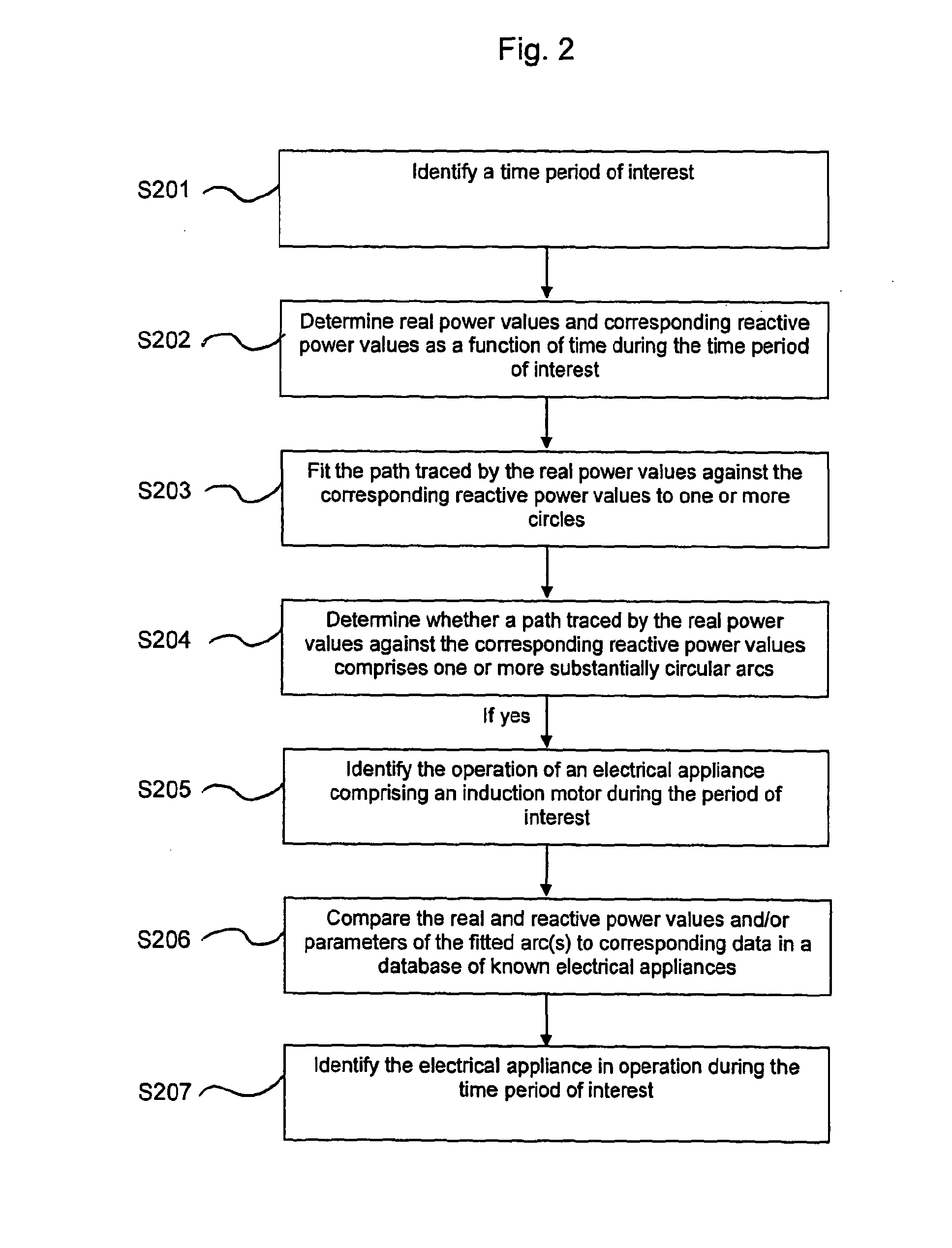
[0052]The method and apparatus of the present invention may be used to identify the operation of an electrical appliance comprising an induction motor. As described in the Summary of the Invention, the methodology uses inherent properties of induction motors to enable their identification and differentiation from other types of electrical appliance (e.g. resistance heaters).

[0053]The Appliance Identification Apparatus

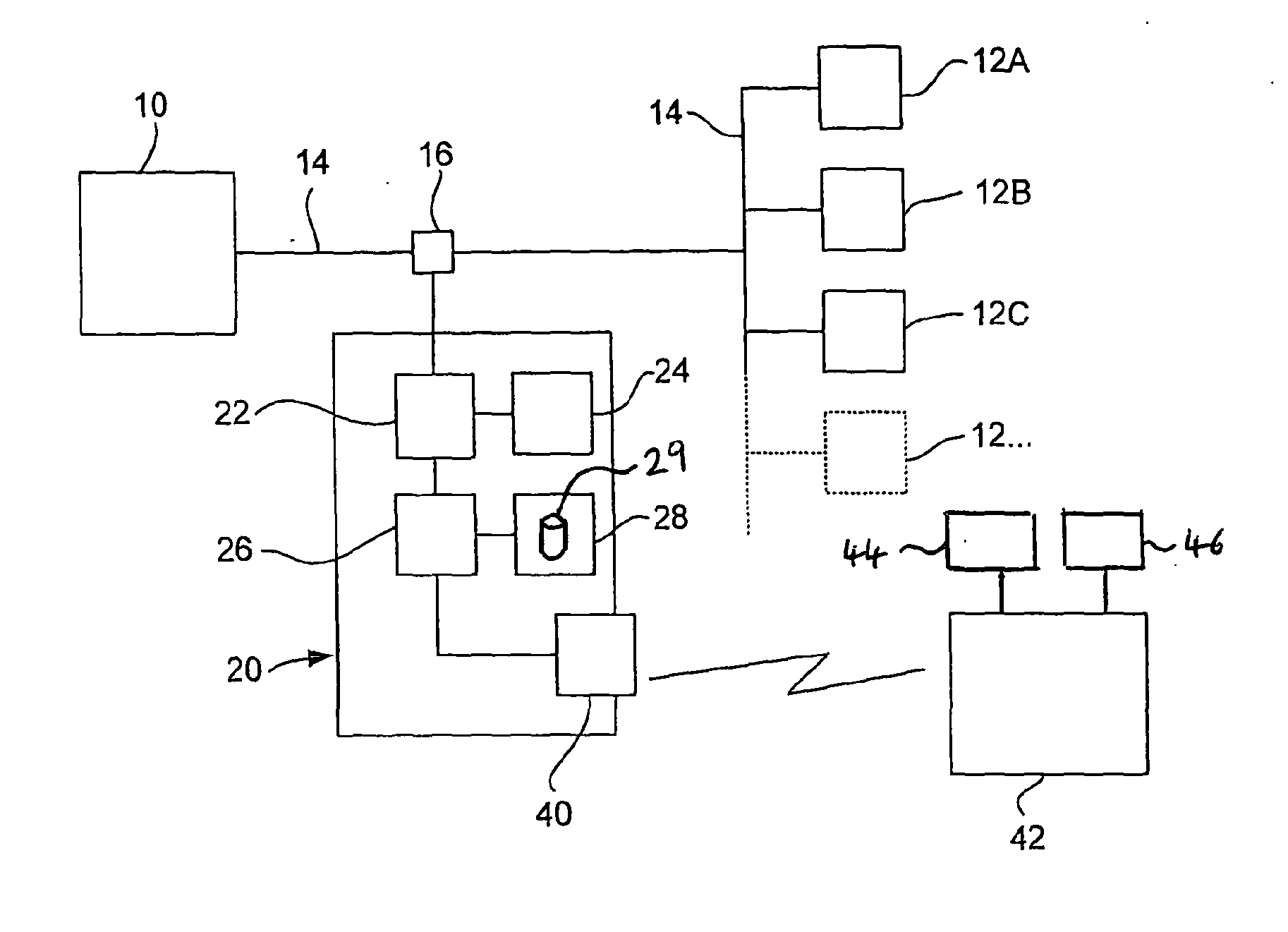
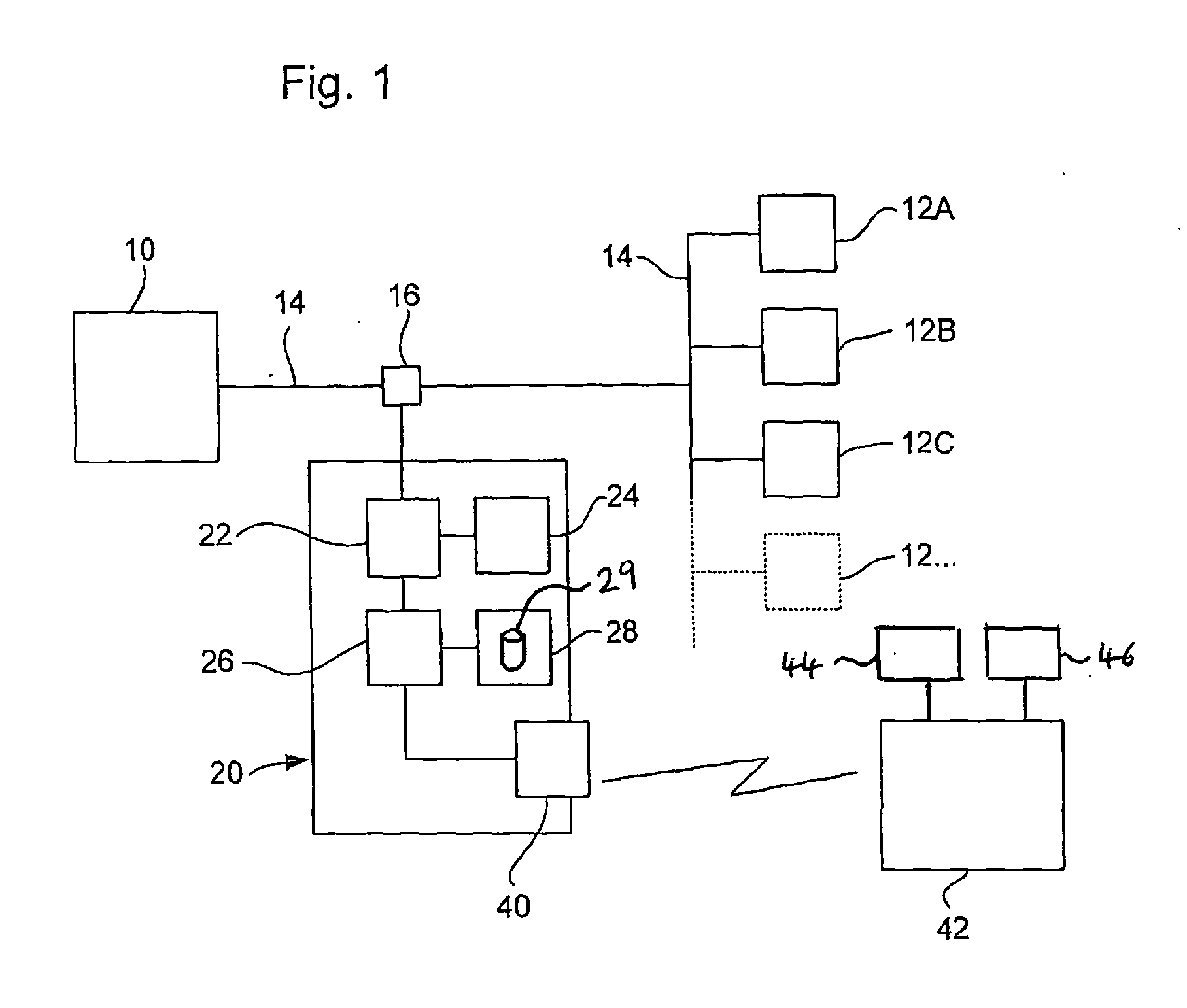
[0054]FIG. 1 shows the hardware components of a system incorporating the apparatus for identifying the operation of an electrical appliance comprising an induction motor. In FIG. 1, the electricity supply to the site, for example a house, apartment, office, shop, school and so forth, is denoted 10. The electricity is supplied to a plurality of electrical appliances 12A, 12B, 12C, 12 . . . by means of conventional wiring 14. The appliances and wiring are simply shown schematically in FIG. 1, but may, of course, be configured in any appropriate way, such as via a consumer...


PUM


Abstract

A method of identifying the operation of an electrical appliance comprising an induction motor is described. The method comprises identifying the operation of an electrical appliance comprising an induction motor when a path traced by real power values against corresponding reactive power values over a time period of interest comprises one or more substantially circular arcs. The real power values are related to the total real power supplied to one or more electrical appliances as a function of time, and the reactive power values are related to the total reactive power supplied to the one or more electrical appliances as a function of time.
There is also described a related method of identifying the operation of a specified type of appliance, in which the operation of said specified type of appliance is dependent on a supply of at least one utility such as electricity, natural gas or water. Corresponding computer programs, computer-readable mediums, computer program products and apparatuses are also described.

Description

FIELD OF THE INVENTION[0001]The present invention relates to a method and apparatus for identifying the operation of a specified type of appliance, in which the operation of that specified type of appliance is dependent on a supply of at least one utility (e.g. electricity, natural gas or water). One embodiment of the present invention relates to a method and apparatus for identifying the operation of an electrical appliance comprising an induction motor.BACKGROUND OF THE INVENTION[0002]There is an increasing concern to reduce the consumption of resources, both at a domestic level in residential buildings, and at a commercial level in offices, shops, factories and so forth. The reasons for this are both to save costs and also because of concerns for the environment, such as to reduce CO2 emissions, and to conserve finite resources such as coal, gas and oil.[0003]Conventionally, consumers receive bills from utility companies which may indicate the quantity of the utility used since t...

Claims


Application Information

Patent Timeline
Patent Type & Authority Applications(United States)
IPC IPC(8): G06F19/00G01R19/00
CPCG01D4/002G01R31/343Y04S20/32Y02B90/241Y04S20/38G01D2204/24Y04S20/30G01R21/00G01R21/1331Y02B90/20
Inventor DONALDSON, JAMESSURRALL, SARAHMATTHEWS, ALEXANDERMCCULLOCH, MALCOLM
Owner SENSUS USA
Why Eureka
Try Eureka