

Sensor and method for operating a sensor
a sensor and sensor technology, applied in the field of sensors, can solve problems such as inability to achieve complete vibration compensation, complex measures, and possible interferen
- Summary
- Abstract
- Description
- Claims
- Application Information
AI Technical Summary
Benefits of technology
Problems solved by technology
Method used
Image

Examples
first exemplary embodiment
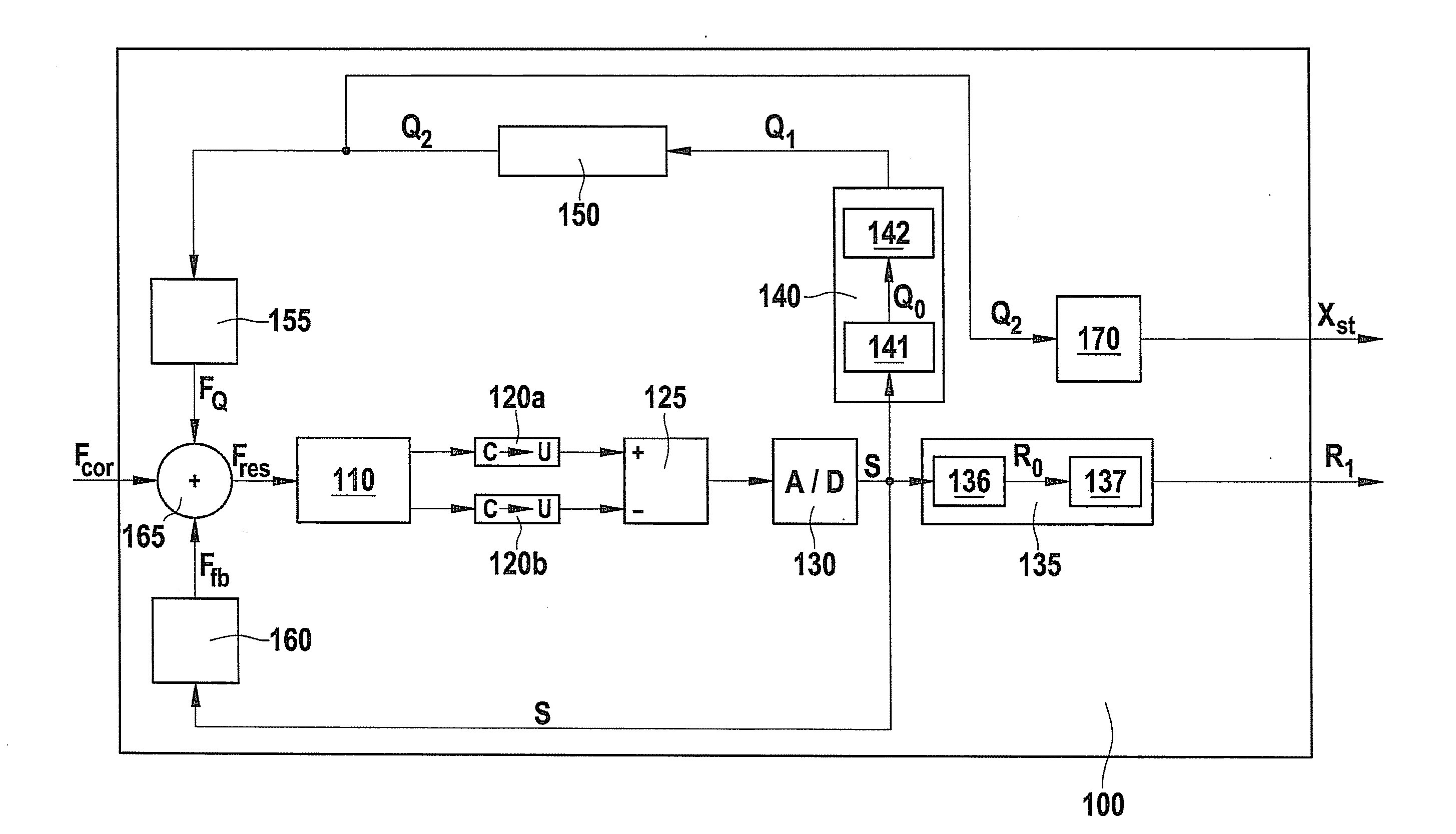
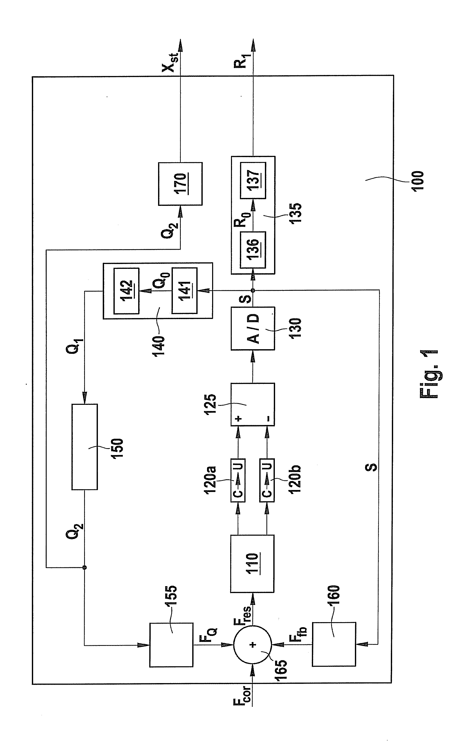
[0040]FIG. 1 is a block diagram which shows the system of a yaw rate sensor 100 according to the present invention as per a first exemplary embodiment.
[0041]The core of sensor 100 is an oscillation mechanism 110. When sensor 100 is pivoted around a specific rotational axis, Coriolis forces act on the measuring electrodes provided in oscillation mechanism 110, which result in a local displacement of the measuring electrodes. This local displacement is measured capacitively and converted as explained below into a rate signal R1, which contains information about the local displacement and therefore the yaw rate acting on the sensor. This is explained in greater detail hereafter.
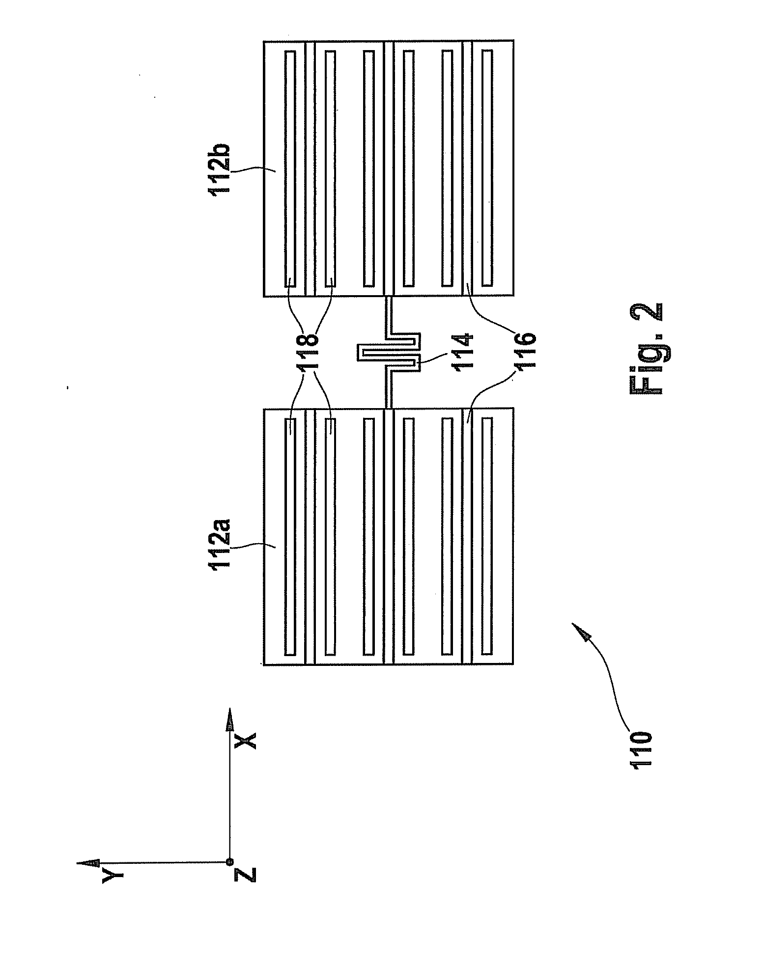
[0042]FIG. 2 is a schematic view of oscillation mechanism 110. In the present example, oscillation mechanism 110 is designed as a two-mass system having two linear oscillators 112a and 112b. The two linear oscillators 112a and 112b are mechanically coupled to one another via a spring 114.
[0043]Each of two linear...
second exemplary embodiment
[0067]FIG. 6 is a block diagram which explains the system of a sensor 200 according to the present invention as per a second exemplary embodiment.
[0068]Components which correspond to those of sensor 100 of the first exemplary embodiment in FIG. 1 are identified by identical reference numerals and are not explained in greater detail. Sensor 200 in FIG. 6 differs from sensor 100 according to the first exemplary embodiment in that a correction circuit 180 is further provided, to which rate signal R1 and quadrature signal Q1 are supplied, and which outputs a corrected rate signal R2. More precisely, correction circuit 180 outputs rate signal R1 unchanged if the value of status signal Xst is “LO,” and outputs a corrected rate signal if the value of status signal Xst is “HI.”
[0069]Furthermore, in this embodiment, in contrast to the first embodiment, the regulation using quadrature controller 150 is stopped as soon as status signal Xst marks a faulty rate signal For this purpose, status si...
PUM
 Abstract
Description
Claims
Application Information