Bandwidth extension method, bandwidth extension apparatus, program, integrated circuit, and audio decoding apparatus

a bandwidth extension and frequency bandwidth technology, applied in the field of bandwidth extension methods for extending the frequency bandwidth of an audio signal, can solve the problems of unfavorable auditory artifact sensation, roughness and unpleasant timbre, and achieve the effect of reducing computation amount and good sound quality

Active Publication Date: 2012-05-31
PANASONIC INTELLECTUAL PROPERTY CORP OF AMERICA
View PDF7 Cites 85 Cited by
  • Summary
  • Abstract
  • Description
  • Claims
  • Application Information

AI Technical Summary

Benefits of technology

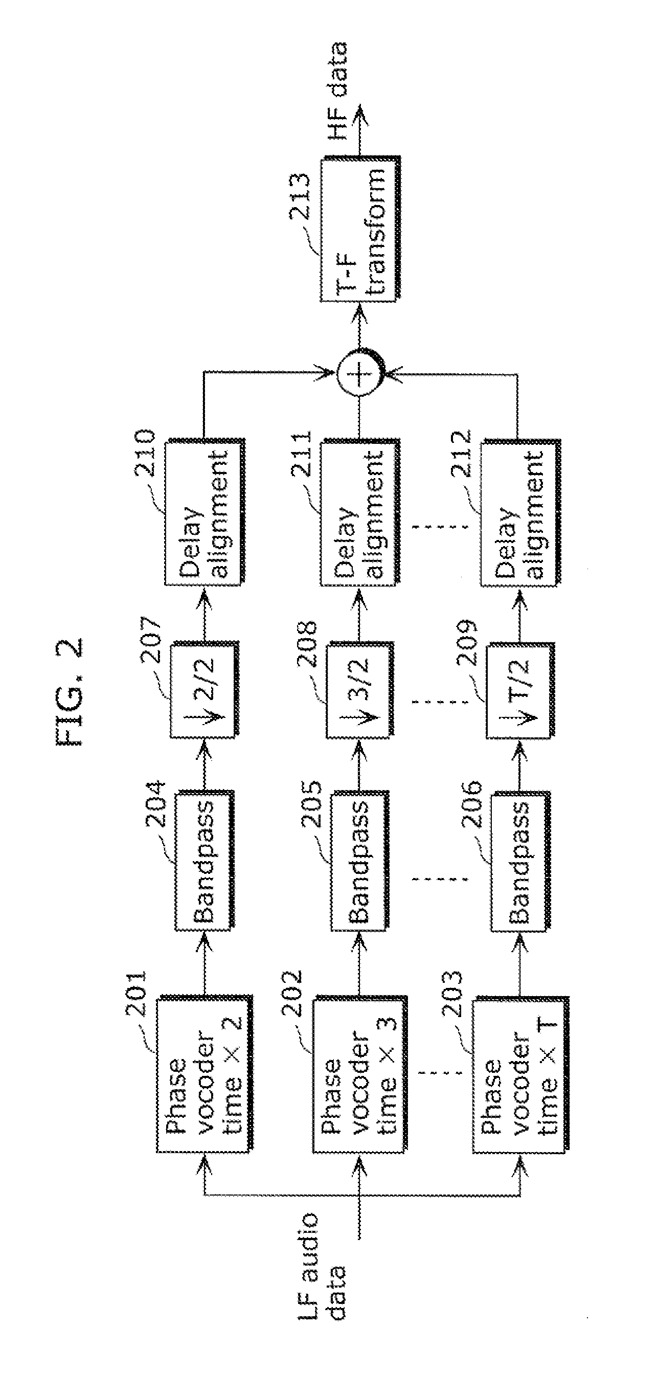
[0055]The bandwidth extension method in the present invention designs a new harmonic bandwidth extension (HBE) technology. The core of the technology is to do time stretching or both time stretching and pitch shifting in QMF domain, rather than in traditional FFT domain and time domain, respectively. Comparing to the prior-art HBE technology, the bandwidth extension method in the present invention can provide good sound quality and significantly reduce the computation amount.

Problems solved by technology

However, at very low bitrates (e.g. <20 kbits / s mono), where only small LF part bandwidths are feasible, such SBR technology can lead to undesired auditory artifact sensations such as roughness and unpleasant timbre (for example, see Non-Patent Literature (NPL) 1).

Method used


Image

  • Bandwidth extension method, bandwidth extension apparatus, program, integrated circuit, and audio decoding apparatus
  • Bandwidth extension method, bandwidth extension apparatus, program, integrated circuit, and audio decoding apparatus
  • Bandwidth extension method, bandwidth extension apparatus, program, integrated circuit, and audio decoding apparatus

Examples


first embodiment

[0075]Hereinafter, a HBE scheme (harmonic bandwidth extension method) and a decoder (audio decoder or audio decoding apparatus) using the same, in the present invention, shall be described.

[0076]FIG. 5 is a flowchart showing the bandwidth extension method in the present embodiment.

[0077]This bandwidth extension method is a bandwidth extension method for producing a full bandwidth signal from a low frequency bandwidth signal, the method including: transforming the low frequency bandwidth signal into a quadrature mirror filter bank (QMF) domain to generate a first low frequency QMF spectrum (hereafter referred to as the first transform step); generating pitch-shifted signals by applying different shifting factors on the low frequency bandwidth signal (hereafter referred to as the pitch shift step); generating a high frequency QMF spectrum by time-stretching the pitch-shifted signals in a QMF domain (hereafter referred to as the high frequency generation step); modifying the high frequ...

second embodiment

[0135]Hereinafter, a second embodiment of the HBE scheme (harmonic bandwidth extension method) and a decoder (audio decoder or audio decoding apparatus) using the same shall be described in detail.

[0136]Note that with adopting of the QMF-based time stretching method, the HBE technology used the QMF-based time stretching method has much lower computation amount. However, on the other hand, adopting the QMF-based time stretching method also brings two possible problems which have risks to degrade the sound quality.

[0137]Firstly, there is quality degradation problem for high order patch. Assume that a HF spectrum is composed with (T-1) patches with corresponding stretching factors as 2, 3, . . . , T. Because the QMF-based time stretching is block based, the reduced number of overlap-add operation in high order patch causes degradation in stretching effect.

[0138]FIG. 10 is a diagram showing sinusoid tonal signal. The upper panel (a) shows the stretched effect of a 2nd order patch for a ...


PUM


Abstract

To provide a bandwidth extension method which allows reduction of computation amount in bandwidth extension and suppression of deterioration of quality in the bandwidth to be extended. In the bandwidth extension method: a low frequency bandwidth signal is transformed into a QMF domain to generate a first low frequency QMF spectrum; pitch-shifted signals are generated by applying different shifting factors on the low frequency bandwidth signal; a high frequency QMF spectrum is generated by time-stretching the pitch-shifted signals in the QMF domain; the high frequency QMF spectrum is modified; and the modified high frequency QMF spectrum is combined with the first low frequency QMF spectrum.

Description

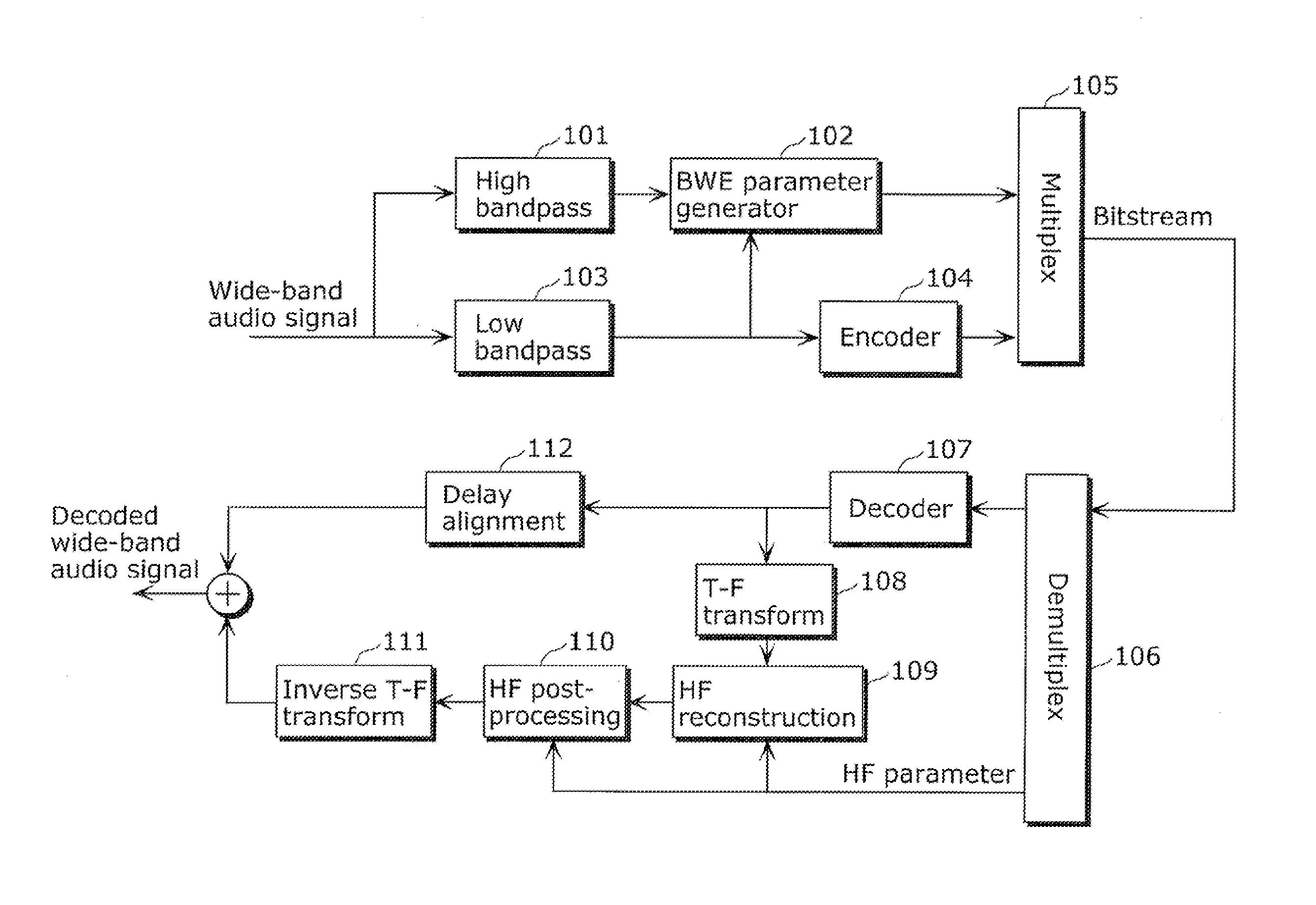
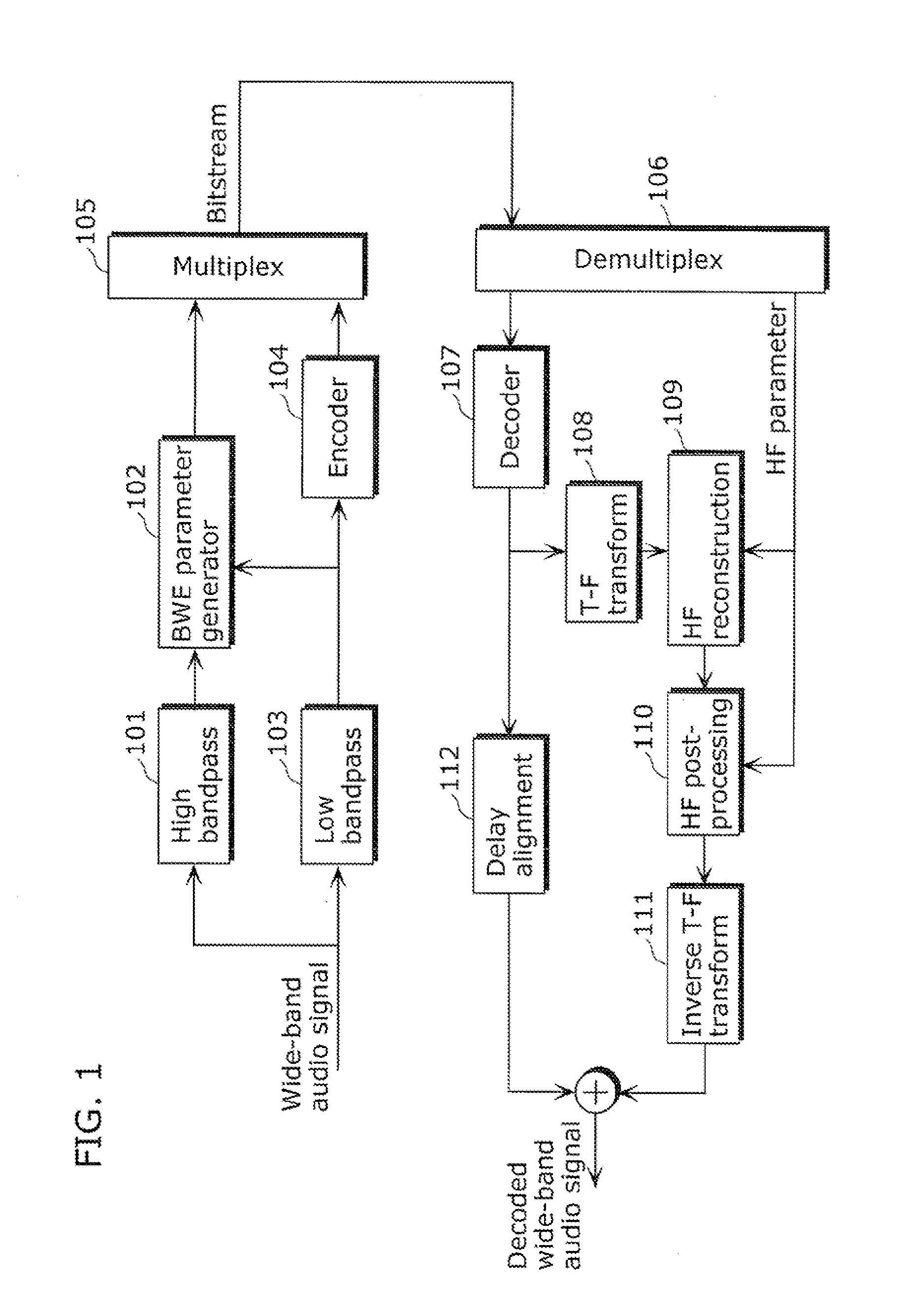
TECHNICAL FIELD[0001]The present invention relates to a bandwidth extension method for extending a frequency bandwidth of an audio signal.BACKGROUND ART[0002]Audio bandwidth extension (BWE) technology is typically used in modern audio codecs to efficiently code wide-band audio signal at low bit rate. Its principle is to use a parametric representation of the original high frequency (HF) content to synthesize an approximation of the HF from the lower frequency (LF) data.[0003]FIG. 1 is a diagram showing such a BWE technology-based audio codec. In its encoder, a wide-band audio signal is firstly separated (101&103) into LF and HF part; its LF part is coded (104) in a waveform preserving way; meanwhile, the relationship between its LF part and HF part is analyzed (102) (typically, in frequency domain) and described by a set of HF parameters. Due to the parameter description of the HF part, the multiplexed (105) waveform data and HF parameters can be transmitted to decoder at a low bit ...

Claims


Application Information

Patent Timeline
Patent Type & Authority Applications(United States)
IPC IPC(8): G10L19/00G10L19/02G10L21/038G10L21/0388G10L21/04
CPCG10L21/04G10L21/038G10L19/02G10L19/0204G10L19/0208G10L21/02
Inventor ISHIKAWA, TOMOKAZUNORIMATSU, TAKESHIZHOU, HUANCHONG, KOK SENGZHONG, HAISHAN
Owner PANASONIC INTELLECTUAL PROPERTY CORP OF AMERICA
Why Eureka
Try Eureka